
Description
Danfoss PVG32‑1 Single‑section Load‑Sensing Proportional Hydraulic Valve Group, Modular Sectional Mobile Proportional Directional Control Valve
Product Core Overview
The PVG32‑1 is a single‑section modular proportional valve group belonging to Danfoss PVG32 series load‑sensing hydraulic valves. It adopts sectional stacked modular construction, integrating inlet pressure‑compensated load‑sensing function to realize load‑independent flow control. The output flow keeps stable regardless of load pressure variation, and multiple sections can be stacked for multi‑actuator compound action.
PVG32‑1 supports multiple actuation options: manual mechanical lever (PVM), hydraulic pilot actuation, and PVE electro‑proportional electric actuation for PLC control signal interface. Built‑in pressure relief valve, shock‑absorbing and anti‑cavitation valve options protect hydraulic cylinders and motors. Widely used for mobile machinery hydraulic systems. PVG32‑1 denotes 1 working section; more sections can be expanded up to max 10 sections per complete valve stack.
Notes:
- Full Danfoss order codes example: 11131752, 11192829; different suffix codes correspond to spool flow, actuation type and valve function variants.
- Load‑sensing LS system compatible, supports open‑center / closed‑center pump circuits.
- Can be configured with load‑drop check valves, shock valves, anti‑cavitation valves according to OEM requirements.
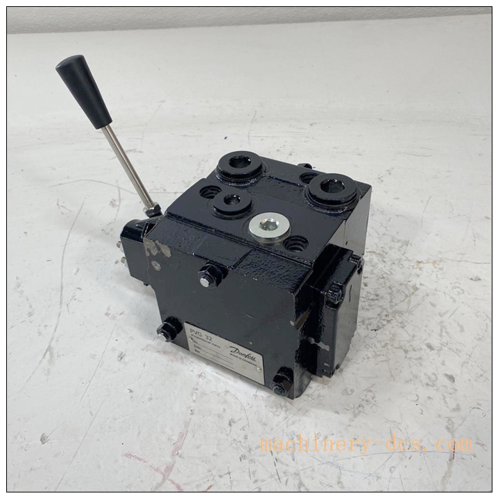
DANFOSS PVG32-1
Main Technical Specifications
| Item | Technical Parameter |
|---|---|
| Part Number | PVG32‑1 (single‑section valve group) |
| Manufacturer | Danfoss (Sauer‑Danfoss) |
| Valve Type | Sectional proportional directional control valve |
| Max continuous inlet pressure | 350 bar (5076 psi) |
| Max intermittent inlet pressure | 400 bar (5800 psi) |
| Max rated flow per section | 130 L/min (34.4 gal/min) with pressure compensator |
| Tank port max pressure | 25‑40 bar |
| Control principle | Load‑independent flow control via individual pressure compensator |
| Actuation modes | Mechanical PVM, hydraulic pilot PVH, electrical proportional PVE (12‑24 VDC) |
| Max stackable sections | Up to 10 working sections in one valve assembly |
| Hydraulic fluid temperature | −30 °C ~ +90 °C; recommended 30‑60 °C |
| Ambient operating temperature | −30 °C ~ +60 °C |
| Recommended oil viscosity | 12‑75 mm²/s |
| Fluid cleanliness requirement | ISO 4406: 18/16/13 (electrical actuation) / 23/19/16 (mechanical) |
| Supply voltage for PVE actuator | 11‑30 VDC (12 V /24 V mobile system) |
| Port type | Threaded ports P, T, LS, A, B |
| Weight | Approx. 4.2 kg (‑1 mechanical manual version) |
| Certifications | CE compliance for mobile machinery |
Related Series & Model Recommendations (8+ Models)
- PVG32‑1: 1‑section proportional valve group, base unit for single‑actuator hydraulic control
- PVG32‑2: Two‑section stacked proportional valve group for dual‑actuator compound operation
- PVG32‑3: Three‑section stacked valve group for multi‑function mobile equipment
- PVP: series pump‑side inlet module, includes LS relief valve, pressure reducing pilot valveassets.dan…
- PVB32: Standard working valve section cartridge for stack assembly
- PVM: Mechanical manual lever actuator module for sections
- PVEA / PVEO: Electrical proportional actuator, 12/24 VDC for PLC analog/PWM control signal
- PVLP: Shock‑absorbing & anti‑cavitation valve cartridge for A/B work ports
- PVS: End‑plate termination module for completing valve stack
- PVG16: Small‑size lower‑flow sibling proportional valve series for compact mobile machines
Professional Quality Control & Factory Test Procedures
- Visual & Mechanical Incoming Inspection: Inspect valve casting body, port thread integrity, lever/actuator assembly, nameplate marking; record serial number for full‑lifecycle traceability. Check zero‑leak plug status.
- Hydraulic Pressure‑holding Test: Apply full rated static pressure to P‑port, verify body sealing, no external leakage across all ports.
- Spool Stroke & Mechanical Actuation Test: Operate manual lever full‑stroke repeatedly, check smooth spool movement without sticking or dead‑band anomaly.
- Load‑sensing Compensator Performance Test: Test pressure‑compensator function under variable load pressure, verify flow keeps stable independent of load change.
- Flow‑characteristic Calibration Test: Measure A/B port output flow at different spool positions, validate proportional flow‑stroke linearity.
- Relief‑valve Setting Test: Adjust and verify inlet LS relief‑valve pressure setting, confirm over‑pressure protection trigger point.
- Channel‑by‑channel Leakage Test: Measure internal spool leakage at rated pressure, meet factory leakage specification.
- Electrical Actuator Test (for PVE version): Apply 0‑10 V / PWM control signal, validate electrical‑proportional spool response.
- Environmental Stress Screening: Temperature‑cycle test covering full hydraulic fluid and ambient temperature operating range.
- Final Full‑function Validation & Archiving: Complete valve‑assembly acceptance test; bind test reports with unit serial‑number before factory release.
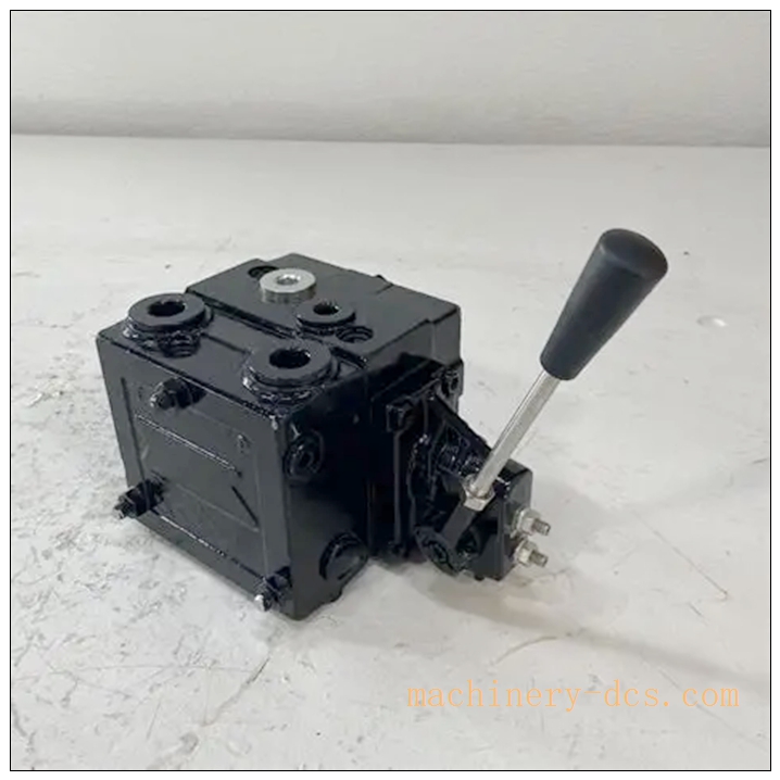
DANFOSS PVG32-1
New Module Installation & Commissioning Guide
6.1 Pre‑installation Preparation
Inspect ‑1 for transit damage, confirm part number and spool configuration matches project requirement. Prepare correct hydraulic fittings, high‑pressure hoses, filter element meeting ISO 4406 cleanliness standard. Isolate pump power and release system residual pressure before installation work.
6.2 Mechanical Installation
Mount ‑1 valve group on rigid machine frame or valve bracket. Respect torque values for stack tie‑rods when assembling multi‑section stacks. Avoid excessive mechanical stress on valve body from hose pulling force. For stacked assemblies, install PVP inlet module at first position and PVS end‑plate at the end of stack.
6.3 Hydraulic Wiring
Connect pump pressure port P, tank return port T, load‑sensing LS port, actuator A/B ports. Use high‑pressure hydraulic hoses matched for 400 bar pressure rating. Keep LS signal line short. Ensure tank line back‑pressure remains below rated value. For PVE electrically actuated version, connect 12‑24 VDC power and control signal cables, separate signal cables from high‑power cables.
6.4 System Commissioning
- Complete full‑system hydraulic oil filling and exhaust air bleeding from valve and actuator loops.
- Set main LS relief‑valve pressure according to machinery design requirement.
- Operate manual lever / send electrical control signal, perform low‑pressure no‑load movement test for cylinder/motor.
- Check A/B port flow performance, adjust flow‑limit screw if needed.
- Run full‑load test, verify load‑independent flow function under varying load conditions.
- Inspect for external leakage, abnormal noise or vibration.
- Confirm shock‑valve and anti‑cavitation valve work correctly under impact load.
- Save pressure‑setting records, put valve assembly into formal machine operation.
Application Scenarios & Product Features
7.1 Application Scenarios
‑1 proportional valve group is widely deployed in mobile machinery: construction loaders, excavator attachments, agricultural harvesters & tractors, forestry cranes, material‑handling equipment, mobile lifting cranes, special‑purpose off‑road OEM machinery and mobile industrial hydraulic systems.
7.2 Core Product Features
- Load‑independent Flow Control: Individual pressure compensator for each section; flow remains stable regardless of actuator load pressure change.
- High‑modular Stackable Design: Single‑section base ‑1 can stack up to 10 sections for multi‑function compound action.
- Multiple Actuation Choices: Manual lever, hydraulic pilot, or PVE electro‑proportional actuation for PLC automation control.
- Integrated Protection Components: Optional built‑in pressure relief, shock‑absorbing, anti‑cavitation and load‑drop check valves.
- LS Load‑sensing Compatibility: Optimized for load‑sensing pump systems to reduce energy consumption and heat generation.
- Wide pressure & flow coverage: Up to 400 bar intermittent pressure and 130 L/min per section flow capacity.
- Robust mobile‑grade design: Adapt to severe vibration, wide temperature range for off‑road mobile equipment environment.
Frequently Asked Questions (FAQ)
Q1: What does ‑1 mean? A: is the series code; suffix‑1 stands for one working section. ‑2 means two stacked sections, and so on up to max 10 sections.
Q2: Why actuator speed changes under heavy load? A: Main possible causes: insufficient pump flow, pressure compensator fault, contaminated hydraulic oil, clogged filter, wrong LS‑relief pressure setting. Check oil cleanliness first.
Q3: Can ‑1 work with PLC analog output? A: Yes, but must install PVE electro‑proportional actuator module. Accepts 0‑10 V analog or PWM control signals from PLC controller. Pure mechanical PVM version cannot be electrically controlled.
Q4: What oil cleanliness level is required? A: For electrical PVE actuation: ISO 4406 18/16/13. For pure mechanical manual actuation: ISO 4406 23/19/16. Poor oil cleanliness will cause spool sticking and proportional drift fault.
Q5: Can I add extra sections to existing ‑1 valve on‑site? A: Theoretically yes. Must disassemble tie‑rods, add PVB working sections, and retorque tie‑rods strictly per Danfoss service manual. After re‑stacking, full hydraulic commissioning and leakage test is mandatory.
Q6: Valve spool sticks, hard to operate manual lever. What are typical causes? A: Contaminated hydraulic oil, dirt particles entering spool clearance, internal component wear, improper tie‑rod over‑torque distorting valve body. Replace filter and flush hydraulic system first.
Q7: Is on‑site disassembly permitted? A: Spool and compensator cartridges are serviceable by trained hydraulic technicians following official Danfoss service manual. Unauthorized disassembly without service documentation may lead to performance deviation and void OEM warranty.

 Start Chat


 Send an Email


