
Description
B&R 8BVI0220HCS0000‑1 ACOPOSmulti Servo Inverter Module
Product Detailed Description
The 8BVI0220HCS0000‑1 is a high‑performance single‑axis inverter module within B&R ACOPOSmulti modular servo drive family, manufactured in Austria. It delivers 22 A continuous effective output current for high‑dynamic servo motor control, supporting cold‑plate or pass‑through wall‑mount cooling architecture for optimal thermal dissipation. This unit integrates Safe Torque‑Off (STO) safety function, motor holding‑brake output, motor temperature sensor input, and provides two internal slots for optional plug‑in encoder & communication expansion cards. It connects to shared DC‑bus power supply modules of ACOPOSmulti system and executes high‑speed vector control for synchronous servo motors. Still available for active order; surplus NOS, refurbished and used pull‑units also circulate in spare‑part market for machine retrofit and maintenance projects。
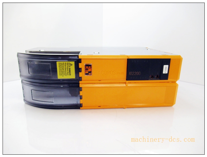
8BVI0220HCS0000-1
Technical Parameters
| Item | Specification |
|---|---|
| Manufacturer | B&R (Br‑Automation, Austria) |
| Model | 8BVI0220HCS0000‑1 |
| Series | ACOPOSmulti |
| Country of Origin | Austria |
| Product Status | Active production, spare‑part accessible |
| Axis Quantity | 1 axis |
| Continuous Output Current | 22 Aeff |
| Peak Output Current | 55 Aeff |
| DC‑Bus Nominal Voltage | 750 VDC (operating range:260‑800 VDC) |
| Switching Frequency | 5 kHz / 10 kHz / 20 kHz configurable |
| Max Output Frequency | 598 Hz |
| Brake Output | 24 VDC, max 4.2 A continuous for motor holding brake |
| Safety Function | Safe Torque‑Off STO, IEC 61800‑5‑2 compliant |
| Expansion Slots | 2 slots for ACOPOSmulti plug‑in option cards |
| Mounting Method | Cold‑plate mounting / pass‑through wall‑mount |
| Permissible Orientation | Vertical hanging / horizontal face‑up; horizontal standing is prohibited |
| Operating Temperature | +5 °C ~ +40 °C nominal, max +55 °C (current de‑rating applies above 40℃) |
| Storage / Transport Temp | ‑25 °C ~ +70 °C |
| Relative Humidity | 5‑85 % RH non‑condensing for operation |
| Protection Class | IP20 |
| Dimension | 106.5 × 317 × 212 mm |
| Weight | Approx. 3.9 kg |
| Certifications | CE, UKCA, UL cULus E225616, KC, EAC |
Compatibility & Installation Pitfalls
Compatibility
- B&R ACOPOSmulti shared DC‑bus power supply modules (e.g. 8BVP series power supply units)
- B&R synchronous servo motors compatible with ACOPOSmulti drive platform
- Option plug‑in cards for encoder feedback, POWERLINK, field‑bus communication
- B&R X20 / APC series PLC motion controller environment via POWERLINK real‑time bus
Important note: This inverter module cannot run standalone. It must pair with ACOPOSmulti DC‑bus power unit and matching motor‑encoder configuration. Different suffix variants (HCS / HCD / HCSA) differ in cooling and feedback interface and are not direct drop‑in replacements.
Installation Pitfalls
- Cooling surface damage risk: Cold‑plate mounting rear metallic contact surface must remain scratch‑free. Scratches degrade thermal conduction and trigger over‑temperature alarms or premature hardware failure.
- Mounting orientation constraint: Horizontal standing installation is strictly forbidden, will cause abnormal heat accumulation and over‑temperature shutdown. Keep ≥60 mm clearance above & below module for thermal circulation.
- DC‑bus hot‑plug prohibition: Never insert/remove module while DC‑bus is energized. High‑voltage residual charge will destroy internal power semiconductors. Execute full power‑down and DC‑bus discharge procedure before replacement.
- Firmware & parameter mismatch: When swapping spare module, old machine project parameters, motor data and drive firmware revision must match. Mismatched firmware leads to axis initialization failure, motor oscillation or over‑current trips.
- Motor brake wiring error: Integrated 24 VDC brake output is dedicated for motor holding brake only. Do not connect external loads beyond rated current; over‑current will burn internal brake drive circuit.
- Encoder option‑card slot mismatch: Two internal expansion slots have different hardware assignment. Wrong slot placement causes feedback channel loss.
- ESD protection requirement: Encoder and control signal terminals are static‑sensitive. ESD wrist strap is mandatory during card insertion‑removal and wiring.
- Part‑number suffix verification: Double‑check full part number 8BVI0220HCS0000‑1. Distinguish from HCD / HCSA derivative models with different mechanical & feedback specs.
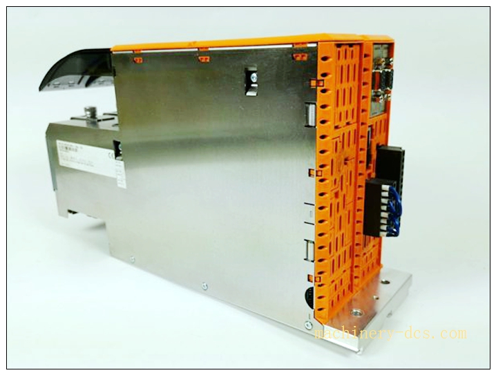
8BVI0220HCS0000-1
Standard Operating Procedure (SOP)
- Pre‑work: Apply lock‑out‑tag‑out permit for machine motion segment. Cut off 3‑phase mains supply to ACOPOSmulti power unit. Wait sufficient time for DC‑bus capacitor full discharge. Wear ESD anti‑static wrist strap.
- Data backup: Connect B&R Automation Studio engineering tool, backup complete machine project, record axis parameters, motor dataset, firmware revision of original drive.
- Module removal: Disconnect motor power cable, brake wiring, encoder cable and DC‑bus connector. Release mechanical locking, extract inverter module carefully. Inspect DC‑bus connector pins for burn or deformation.
- Incoming inspection: Visual check spare unit rear cooling plate for scratches, housing damage, confirm full part‑number marking and hardware revision.
- Mechanical mounting: Install module to cold‑plate / pass‑through mounting base, ensure rear metal surface fits flat against cooling plate, fasten mounting screws to specified torque. Follow correct mounting orientation.
- Wiring & option‑card setup: Install required encoder / communication plug‑in cards into correct slots. Reconnect DC‑bus, motor power, brake, temperature‑sensor and feedback cables strictly per wiring diagram.
- Power‑on commissioning: Restore main power supply. Verify drive booting status. If firmware version inconsistency exists, perform firmware upgrade / downgrade. Download saved project parameters and motor data.
- Functional validation: Execute motor static identification procedure. Run low‑speed jog test, check torque, speed and position loop performance. Verify STO safety‑off function test. Confirm no over‑temperature, over‑current or communication alarms.
- Documentation: Fill commissioning log, store defective removed module properly. Release lock‑out‑tag‑out permit only after full‑axis acceptance test passed.
Application Scenarios
‑ High‑dynamic packaging machinery: multi‑axis synchronizing, cutting, sealing, indexing positioning control ‑ Machine‑tool & CNC automation: spindle and feed‑axis high‑precision motion control ‑ Automotive assembly production‑lines, robotic handling equipment ‑ Printing & converting machinery, textile high‑speed tension‑control equipment ‑ Plastic injection & blow‑molding machine servo axes ‑ Retrofit & upgrade of existing production machines with ACOPOSmulti drive platform
Matching & Supporting Components
- ACOPOSmulti 8BVP series shared DC‑bus power supply module
- B&R servo motor with matching encoder feedback interface
- Encoder / POWERLINK / field‑bus plug‑in option cards
- Shielded motor power cable, shielded encoder feedback cable
- B&R Automation Studio engineering software & download link
- Cold‑plate cooling assembly or pass‑through mounting accessories
Brand‑Related Alternative & Recommended Models
- 8BVI0220HCD0000‑1: Variant with different cooling configuration, verify mechanical fit before substitution
- 8BVI0220HCSA0000‑1: SinCos feedback version of same‑current‑rating inverter module
- ACOPOS P3 series: New‑generation B&R servo drive platform for full‑system migration projects

 Start Chat


 Send an Email


