
Description
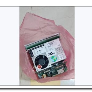
B&R 3AM051.6 Analog Mixed I/O Module, 4AI / 4AO, 0–20mA, 12-bit for System 2005 PLC Rack
Product Description
The 3AM051.6 is a mixed analog input and output module within the B&R System 2005 automation platform. It integrates four differential analog input channels and four short-circuit protected analog output channels for 0–20mA industrial current signals. With 12-bit A/D and D/A conversion, it delivers stable signal acquisition and setpoint control for field transmitters, valves and analog actuators. The module communicates with the System 2005 CPU via the backplane bus, supports cyclic data exchange, on-board channel diagnostics and status LED indication. It requires a separate TB170 terminal block for field wiring termination and is widely used for retrofit and spare replacement of legacy B&R System 2005 control racks.
Technical Specifications
- Brand: B&R (Bernecker + Rainer)
- Part Number: 3AM051.6
- Series: System 2005
- Module Type: Mixed Analog I/O
- Analog Inputs: 4 channels, differential, 0–20 mA
- Analog Outputs: 4 channels, 0–20 mA, short-circuit proof
- Resolution: 12-bit for both AI and AO
- Accuracy: ±0.1% FS (Input, 25°C); ±0.15% FS (Output, 25°C)
- Power Supply: 24 VDC auxiliary power; total power consumption approx. 6.5 W
- Termination: Matched TB170 terminal block
- Diagnostics: Channel open-circuit, short-circuit, module self-test, backplane communication fault
- Status Indication: Module RUN/FAULT LED, channel diagnostic LEDs
- Operating Temperature: 0 °C ~ +60 °C
- Storage Temperature: -20 °C ~ +70 °C
- Relative Humidity: 5% ~ 95 %, non-condensing
- Mounting: Slot mounting inside System 2005 rack
- Weight: Approx. 0.32 kg
- Compliance: CE, industrial EMC standards
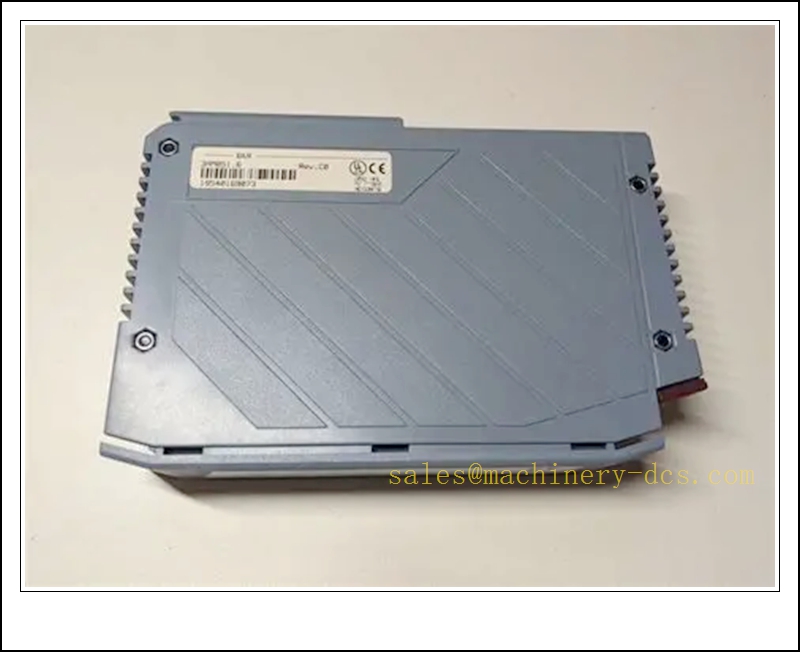
3AM051.6
Application Scenarios
- Packaging machinery analog sensor and proportional valve control
- Plastic injection molding machine pressure and temperature closed-loop regulation
- Material handling and conveyor speed analog setpoint control
- Water treatment plant flow, level and pH transmitter signal acquisition
- HVAC central plant analog actuator and sensor monitoring
- Textile machinery tension and speed analog regulation
- Retrofit and maintenance of legacy B&R System 2005 automation racks
- General factory automation analog measurement and control loops
8 Related B&R Model Recommendations
- 3AM050.6 – System 2005 Analog Input Module
- 3AM052.6 – System 2005 Analog Output Module
- 3DI476.6 – Digital Input Module for System 2005
- 3DO480.6 – Digital Output Module for System 2005
- 3CP260.60-1 – System 2005 CPU Processor
- 3PS465.9 – System 2005 Power Supply Module
- TB170 – Terminal Block for 3AM051.6
- 3IF613.9 – Communication Interface Module for System 2005
Compatibility & Installation Pitfalls
Compatibility
- Designed exclusively for B&R System 2005 rack architecture; not compatible with X20, X67 or APROL series.
- Must pair with TB170 dedicated terminal block; generic terminal adapters cause signal drift and diagnostic failure.
- Backplane firmware and CPU firmware must support System 2005 analog module mapping; outdated firmware triggers I/O identification faults.
- Only supports 0–20mA current signals by default; it cannot directly read RTD, thermocouple or ±10V voltage signals without external signal converters.
- Backplane slot addressing must match the PLC hardware configuration; incorrect slot mapping leads to loss of channel data.
- It cannot be hot-swapped while the rack is powered in most System 2005 configurations.
Installation Pitfalls
- Isolate rack 24VDC supply before module removal or insertion; live insertion may damage backplane bus circuitry.
- Analog 0–20mA field cables must use shielded twisted pairs and be routed separately from high-power motor and inverter cables to avoid EMI noise.
- Maintain correct differential wiring polarity at TB170; reversed input polarity results in negative or unstable measured values.
- Output channels are short-circuit protected, but sustained short-circuit conditions will latch the channel into fault status and stop control output.
- Do not mix analog signal wiring with digital 24V discrete wiring in the same cable trunking.
- Keep the rack ventilation clear; high cabinet ambient temperature worsens measurement accuracy and triggers over-temperature faults.
- Check terminal screw torque on TB170; loose field terminals create intermittent signal jumps that are difficult to diagnose.
- After replacement, download the hardware configuration to the System 2005 CPU; a new module does not retain previous channel scaling parameters.
Standard Operating Procedure (SOP)
SOP for 3AM051.6 Analog Mixed Module Inspection, Installation and Functional Test
- Pre-Installation Inspection Examine the module housing, connectors and PCB for physical damage, burnt components or contamination. Confirm part number 3AM051.6. Verify compatibility with System 2005 CPU, rack backplane and terminal block. Review I/O wiring drawings, sensor and actuator loop details. Apply lockout-tagout to the rack 24VDC control supply and isolate analog field loops as required.
- Rack Installation Insert the 3AM051.6 module into the designated System 2005 rack slot and lock the module latch. Mount and wire the terminal block. Terminate 0–20mA transmitter inputs and proportional valve outputs to the terminal block. Route shielded analog cables away from high-energy power wiring and implement EMC shielding grounding per B&R documentation.
- PLC Hardware Configuration Restore 24VDC rack power. Open B&R programming software, add the 3AM051.6 to the System 2005 hardware tree and assign the correct rack slot address. Configure channel scaling, filtering and fault alarm parameters for each AI/AO point. Compile and download the hardware configuration and application program to the CPU. Save the project and parameter set to offline backup. Resolve backplane or module identification alarms before field signal testing.
- Channel and Diagnostic Test Inject calibrated 4mA, 12mA and 20mA reference signals to each analog input channel and verify scaled readings within specified accuracy tolerance. Force each analog output to 4mA, 12mA and 20mA setpoints and confirm corresponding field actuator response. Simulate open wire and short-circuit conditions to validate fault alarm reporting. Record measurement accuracy and diagnostic response in the test log.
- Closed-Loop Commissioning Remove field signal isolation only after point-level testing passes. Enable automatic control loops and verify closed-loop regulation for pressure, temperature or flow control. Monitor signal stability during machine operation. Confirm channel faults trigger diagnostic alarms and apply predefined safe output states without uncontrolled actuator movement.
- Return to Service Reset fault latches and acknowledge diagnostic messages. Remove lockout-tagout. Monitor module status, bus communication and analog signal quality during the supervised observation window. Notify operations that the 3AM051.6 mixed analog module is commissioned and ready for automatic process control.
- Periodic Maintenance and Replacement During scheduled downtime, inspect rack cooling, terminal torque, cable shielding and connector condition. Perform analog channel calibration and loop proof-test per machine maintenance schedule. If persistent unrecoverable bus or channel faults occur, lock out the rack power before module replacement. After replacement, reload hardware configuration, re-scale channels and complete full point and loop test before releasing the machine to production.

 Start Chat


 Send an Email


