
Description
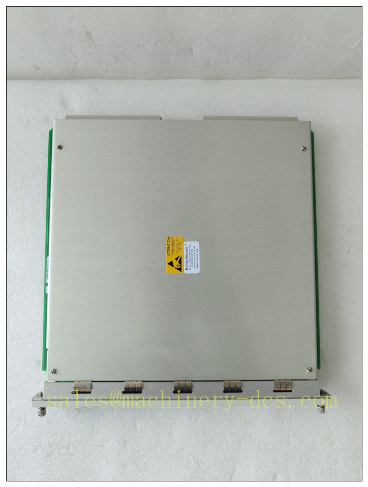
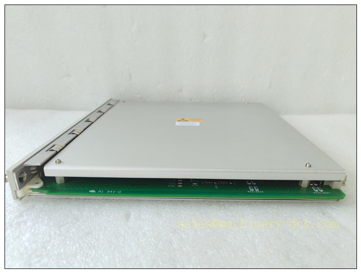
Bently Nevada 3500/33 SIL201-00 4-Channel Relay Module, SIL 2 Rated
Product Description
The 3500/33 SIL201-00 is a relay output module belonging to the Bently Nevada 3500 machinery protection monitoring system. It provides four independent relay outputs for critical machinery alarm and trip functions. This variant is certified for SIL 2 safety applications, designed to interface with vibration, position, speed and other monitoring parameters from the 3500 rack. Each relay can be configured as normally energized or de-energized to meet safety trip logic. It supports latching or non-latching relay operation, with status feedback to the 3500 framework. The module executes protection voting and relay drive logic locally, delivering fast response for rotating machinery safety trips in hazardous and continuous-process environments. It plugs into the 3500 series rack backplane and communicates via the rack’s internal bus with other monitoring modules, power supplies and interface cards.
Technical Specifications
- Brand: Bently Nevada
- Model: 3500/33 SIL201-00
- Number of Relay Channels: 4 independent relays
- SIL Rating: SIL 2
- Relay Contact Type: Electromechanical relay
- Contact Rating: 5 A @ 125 VAC; 5 A @ 30 VDC resistive load
- Module Bus Interface: 3500 rack internal backplane bus
- Operating Temperature: 0 °C to +60 °C
- Storage Temperature: -40 °C to +85 °C
- Relative Humidity: 5% to 95% non-condensing
- Enclosure: Designed for installation in standard 3500 rack chassis
- Configuration: Set via 3500 Rack Configuration Software
- Relay Modes: Latching / Non-latching, Normally Energized / Normally De-energized
- Response Time: Millisecond-scale trip response for machinery protection
- Certification: SIL 2 functional safety certification
- Power Supply: Powered from 3500 rack power supply (24 VDC rack supply)
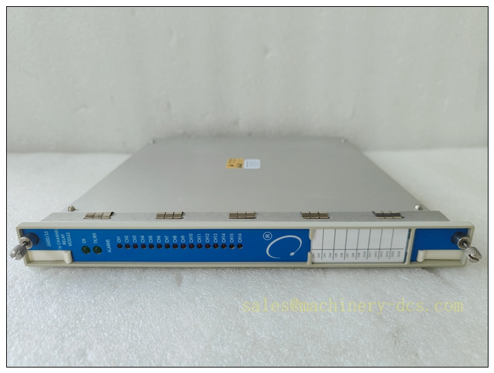
3500/33 SIL201-00
Application Scenarios
- Turbine machinery protection for steam turbines, gas turbines
- Centrifugal and reciprocating compressor vibration & overspeed trip systems
- Large industrial pumps, fans and blowers condition monitoring and alarm trip
- Oil & gas upstream and downstream rotating equipment safety systems
- Power generation plant critical rotating machinery protection
- Petrochemical continuous process machinery SIL 2 safety interlock
- Refinery and chemical plant machinery shutdown systems
- Heavy industry rotating equipment predictive protection racks
8 Related Bently Nevada Model Recommendations
- 3500/42M – 4-Channel Vibration / Position Monitor
- 3500/40M – 4-Channel Speed Monitor
- 3500/45 – Position Expand Monitor
- 3500/32 – 4-Channel Relay Module (non-SIL variant)
- 3500/15 – Dual Power Supply Module
- 3500/20 – Rack Interface Module
- 3500/92 – Communication Gateway Module
- 3500/05 – Rack Chassis Assembly
Compatibility & Installation Pitfalls
Compatibility
- Only compatible with Bently Nevada 3500 series rack backplane and 3500 configuration software.
- Must match compatible firmware revisions for the rack interface module, power supply and other monitoring cards.
- Works with standard 3500 transducer inputs: eddy current probes, velocity transducers, speed probes.
- SIL201-00 SIL-rated version cannot be mixed with non-SIL qualified modules in the same safety protection loop for SIL 2 safety functions.
- Check part revision level; older hardware revisions may not support SIL 2 firmware features.
Installation Pitfalls
- Do not hot-swap the module while the rack is in a live safety trip loop; this may cause unintended relay state changes.
- Relay contact wiring must strictly follow de-energized-to-trip safety logic for SIL 2 applications; miswiring will defeat safety integrity.
- Avoid routing relay output cables alongside high-power variable-frequency drive cables to prevent induced noise and false trips.
- Do not exceed relay contact electrical ratings; overloading contacts causes premature contact degradation and loss of trip function.
- Verify rack firmware compatibility before inserting the SIL-rated relay module; incompatible firmware can disable SIL certification status.
- Module slot assignment matters: do not place safety-related relay modules in spare non-configured slots without validating rack bus resource allocation.
- Ensure proper rack grounding; poor protective earth connection increases EMI susceptibility and risk of false alarms.
- Latching relay logic requires external reset signals; missing reset wiring leaves relays latched after a trip event.
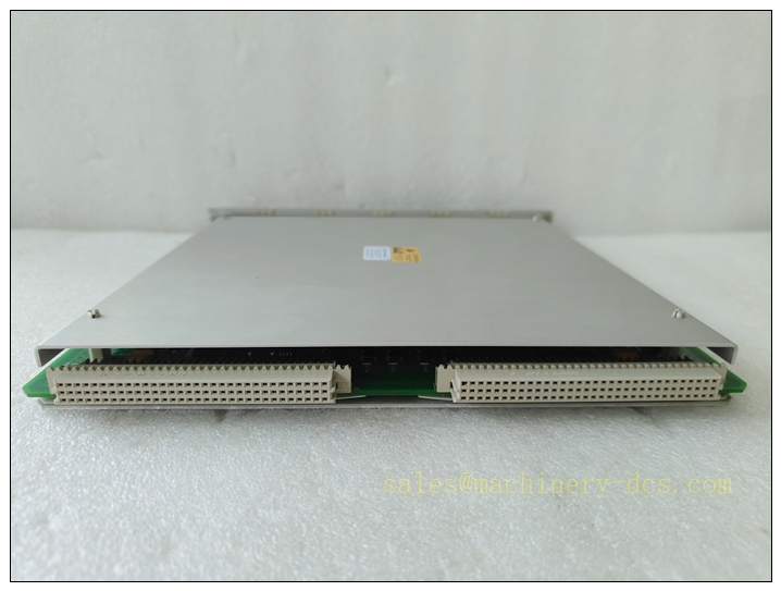
3500/33 SIL201-00
Standard Operating Procedure (SOP)
SOP for 3500/33 SIL201-00 Module Installation, Configuration and Functional Test
- Pre-installation inspection Inspect the module for physical damage, verify part number and SIL marking. Confirm rack firmware, configuration software version and compatible rack hardware revision. Isolate the machinery safety loop and lock out relevant trip circuits before rack work.
- Rack installation Power down the 3500 rack. Insert the 3500/33 SIL201-00 module firmly into the designated backplane slot and secure the module retaining screw. Restore rack power only after all module connections are mechanically seated.
- Software configuration Launch the Bently Nevada 3500 configuration software, read the existing rack configuration. Add the relay module to the slot map. Assign each relay channel to the correct monitor alarm or trip parameter. Select relay operating mode: latching or non-latching, energized or de-energized. Download the validated configuration to the rack and confirm no configuration fault codes. Save the SIL safety configuration file for audit and traceability.
- Wiring and termination Terminate field trip wiring to the relay terminal block in accordance with approved SIL loop drawings. Torque terminals to manufacturer specified values. Separate low-level transducer wiring and high-power relay output wiring with cable segregation. Implement proper shielding and equipment grounding.
- Functional bench and loop test Perform module self-test via rack diagnostics. Force corresponding alarm/trip conditions on the associated monitor channels. Verify relay state changes match configured logic. Confirm contact status feedback in the 3500 display and software. Test latching relay reset function with the designated reset input. Record all test results in the functional safety test log.
- Return to service Clear all fault and latch conditions. Remove lockout tags. Restore the machinery protection loop to online service. Monitor rack status for a minimum observation period to confirm no intermittent faults or spurious relay operation.
- Maintenance and periodic test Conduct periodic relay contact and logic testing per site SIL safety plan. Inspect terminals for loosening or corrosion during shutdown outages. Replace the module immediately if self-test failures, contact degradation or diagnostic faults are detected. Retest the full trip loop after replacement.

 Start Chat


 Send an Email


