Bently Nevada 3500/22M Transient Data Interface (TDI) Module, Industrial Automation Spare Part
- 3500/20 (RIM Rack Interface Module)
- 3500/15 Power Supply
- 3500/40M Proximity Monitor
- 3500/42M Velocity / Acceleration Monitor
- 3500/45M Temperature Monitor
- 3500/50M Tachometer Module
- 3500/53M Relay Module
- 3500/92 Communication Gateway
- 3500/94 Display Module
- 3500/05 System Rack
- 136711-01 Probe
- 330104 Probe
- 330780 Extension Cable
- 3500/60M Overspeed Module
- 3500/62M Overspeed Module
This product is already in your quote request list.
Description
Bently Nevada 3500/22M Transient Data Interface (TDI) Module, Industrial Automation Spare Part
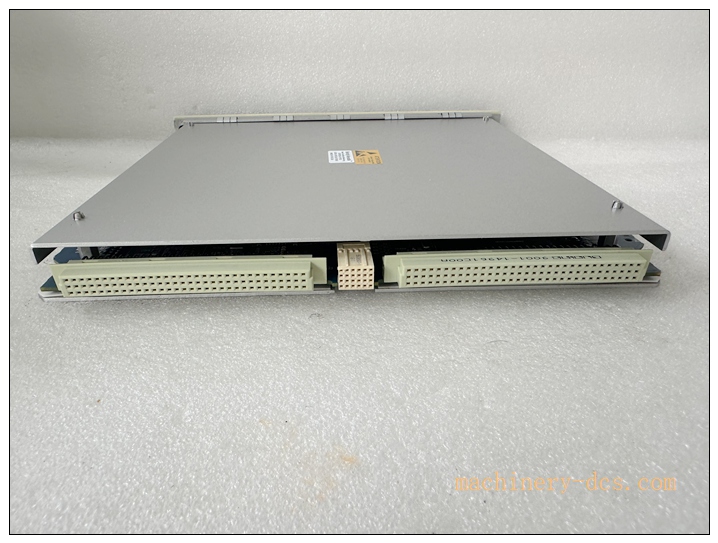
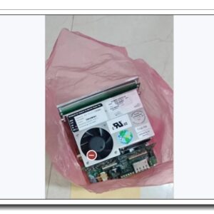
 is a core rack interface module for the Bently Nevada 3500 machinery protection and vibration monitoring system. It integrates the functions of the legacy 3500/20 RIM rack interface and transient data acquisition processor. Installed in Slot 1 next to the rack power supply, it communicates with all M-series monitor cards inside the 3500 rack, uploading static vibration values, waveform, pre/post alarm transient and start-up/coast-down data to System 1 condition monitoring software. It also supports local rack configuration via front USB port. This module <strong>does not belong to the safety trip protection path</strong>, so vibration protection measurement will not be interrupted if the TDI fails. It is widely deployed on steam turbines, gas turbines, compressors and large rotating equipment in power, petrochemical and refining plants. The 3500/22M is end-of-life and supplied as original surplus or fully tested refurbished spare parts for existing 3500 TSI racks.</p>
<div id=)
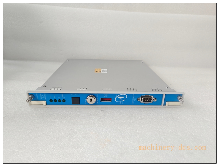
3500/22M
Main Technical Specifications
| Item |
Specification |
| Brand |
Bently Nevada (Baker Hughes) |
| Model |
3500/22M |
| Part No. |
138607-01 |
| Series |
3500 Machinery Protection System |
| Product Type |
Transient Data Interface (TDI) |
| Power Consumption |
10.5 W |
| Front Interface |
USB-B for local configuration, rack reset button, configuration key lock |
| Rear Communication |
10/100Base‑TX copper Ethernet; optional 100Base‑FX fibre Ethernet |
| Supported Monitors |
3500/40M, 3500/42M and other M-series monitor modules |
| Dynamic Acquisition |
Up to 48 waveform channels (requires optional enabling license) |
| Keyphasor |
Supports speed input up to 20 kHz |
| Relay Output |
OK relay, 5A @ 24VDC / 120VAC |
| Operating Temperature |
-30 ℃ ~ +65 ℃ |
| Ambient Humidity |
5%–90% RH, non-condensing |
| Protection Rating |
IP20, for 3500 rack internal installation |
| Mounting |
Fixed in Slot 1 (adjacent to power supply) of standard 3500 rack |
| Diagnostic |
OK, TX/RX, TM, CONFIG OK status LEDs |
| Certification |
UL, CSA, ATEX / IECEx Zone 2 |
| Application |
Turbine, centrifugal compressor, pump, fan vibration monitoring & diagnostic |
Quality Control Procedure
- Visual Incoming Inspection: Check front panel, USB port, reset button, rack edge connector, label, serial number and PCB condition.
- ESD Controlled Handling: All inspection and testing performed on grounded anti-static workstation with ESD wrist strap.
- Power-on Burn-in Test: Install into a compatible 3500 rack, energise continuously for 4 hours; monitor LED status and temperature.
- Rack Backplane Communication Test: Verify handshake and data exchange with all M-series monitor cards in the rack.
- Communication Interface Test: Validate USB local configuration and Ethernet link to System 1 host.
- Data Capture Test: Check static value reading, waveform and transient alarm data upload function.
- Relay & Key Lock Function Test: Verify OK relay action and configuration lock switch.
- Firmware Compatibility Check: Confirm firmware version matches the existing 3500 rack configuration.
- Data Archiving: Record serial number and full test report, attach inspection sticker, vacuum anti-static packaging.
- Pre-shipment Audit: Double-check model and copper/fibre variant before dispatch.
Recommended Related Models & Order Codes (15pcs)
- 3500/20 (RIM Rack Interface Module)
- 3500/15 Power Supply
- 3500/40M Proximity Monitor
- 3500/42M Velocity / Acceleration Monitor
- 3500/45M Temperature Monitor
- 3500/50M Tachometer Module
- 3500/53M Relay Module
- 3500/92 Communication Gateway
- 3500/94 Display Module
- 3500/05 System Rack
- 136711-01 Probe
- 330104 Probe
- 330780 Extension Cable
- 3500/60M Overspeed Module
- 3500/62M Overspeed Module
Frequently Asked Questions
Q1: Can 3500/22M replace 3500/20 RIM directly?A: 3500/22M can substitute 3500/20; it inherits rack interface functions and adds transient waveform capture. Confirm rack firmware and System 1 software version before replacement.
Q2: Is this module discontinued?A: Yes, Bently Nevada 3500/22M is end-of-production. Available stock is original surplus or fully tested refurbished spare parts.
Q3: Does 3500/22M support hot swap?A: The 3500 rack supports hot swap of this module. But transient data upload and remote configuration will be interrupted during replacement; vibration protection channels remain active. Follow plant safety procedures.
Q4: CONFIG OK or link fault alarm after installation, what should I check?A: Check rack power supply, backplane contact, Ethernet cable, IP address setting, System 1 host connection, rack configuration and TDI firmware. Use 3500 configuration software to read rack diagnostics.
Q5: Warranty terms?A: Original surplus new: 12-month warranty. Refurbished tested stock: 6-month warranty. Damage caused by overvoltage, ESD, misconfiguration or incompatible rack firmware is excluded.
Q6: Commissioning software?A: Bently Nevada 3500 Configuration Software and System 1 Machinery Condition Monitoring Software. Back up the full rack configuration before replacement.
Installation & Configuration Guide
Pre-installation Preparation
- Confirm cabinet environment: clean, low dust, no condensation, separated from high EMI sources.
- Prepare ESD protection, insulated screwdriver, Ethernet cable, USB configuration cable and rack project backup.
- Record rack configuration, IP address and System 1 node information before removing the faulty TDI.
Installation Steps
- Follow site LOTO and rotating equipment safety procedure.
- Release the module latch, pull out the old 3500/22M vertically from Slot 1 beside the power supply.
- Unpack new spare under ESD protection; avoid touching backplane gold fingers.
- Insert the new TDI smoothly into Slot 1 and lock the latch.
- Connect rear Ethernet cable and front USB cable only for configuration; separate network cable from high-voltage wiring.
- Verify rack protective earth connection.
Configuration & Commissioning
- Observe front panel LED status after hot insertion.
- Connect PC via USB or Ethernet, launch 3500 configuration software and read rack information.
- Confirm all monitor cards are recognised, verify rack configuration matches the backup.
- Set TDI IP address, connect to System 1 server and confirm online status.
- Test static vibration value, waveform capture and pre/post alarm data upload.
- Check OK relay status and key lock function.
- Clear all rack alarms after self-diagnosis passes.
- Restore normal condition monitoring and save commissioning log.
Maintenance Notes
- The TDI does not affect machine trip protection, but it is critical for vibration trending and fault diagnosis.
- Keep rack ventilation unobstructed; overheating causes intermittent communication dropout.
- Do not modify configuration key lock during normal running.


 Send an Email