

Description
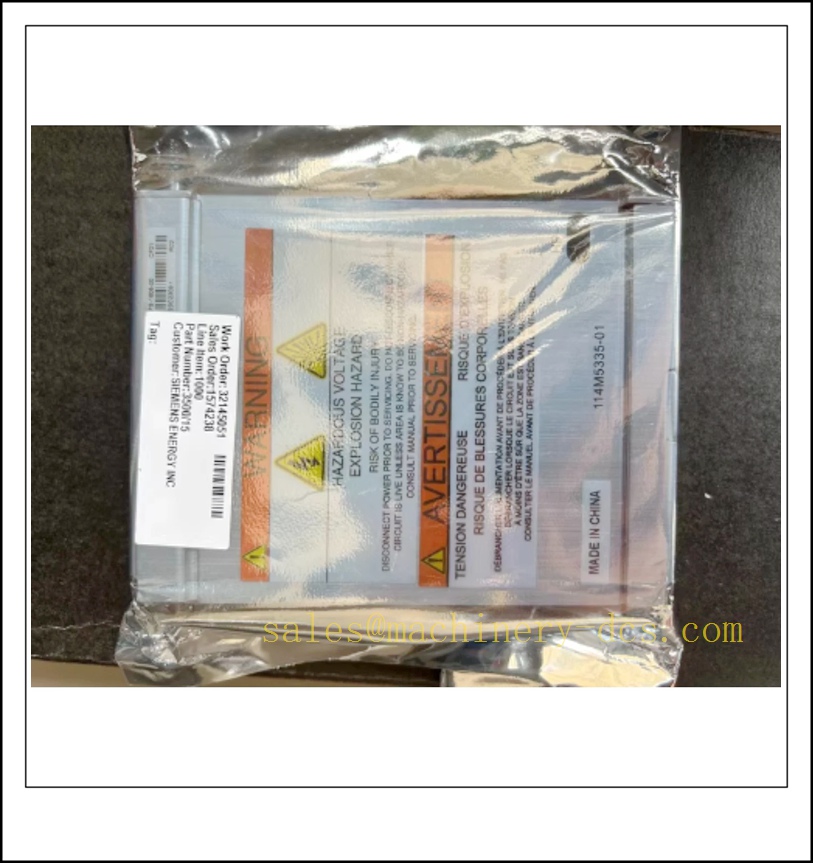
Bently Nevada 3500/15-05-05 Dual Universal AC Redundant Power Supply Module for 3500 Machinery Protection Rack
Product Description
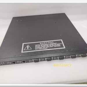
The 3500/15-05-05 is a half-height dual universal AC power supply designed exclusively for the Bently Nevada 3500 machinery protection system. This model is configured with two identical universal AC supply slices, supporting redundant rack power architecture. It converts wide-range AC mains into regulated internal rack bus voltages to feed all monitor, relay, communication and interface modules inside the 3500 chassis. The unit features hot-swap capability; when redundancy is implemented, one supply may be removed or replaced without rack shutdown, which is critical for continuous machinery protection loops. Built-in line filtering, under/overvoltage lockout and diagnostic status LEDs help operators quickly identify supply faults. This power module does not store rack configuration data; configuration resides in the rack interface module, so replacement does not require re-downloading monitoring logic. It must be fitted into the dedicated left-hand power slots of a 3500/05 rack chassis.
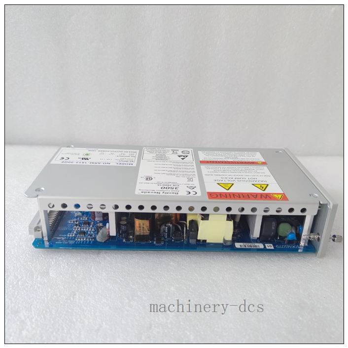
3500/15-05-05
Technical Specifications
- Brand: Bently Nevada
- Model: 3500/15-05-05
- Form Factor: Half-height rack module, dual AC slices
- Input Type: Universal AC for both upper and lower slices
- Input Voltage: 85–264 VAC RMS
- Input Frequency: 47 Hz to 63 Hz (50/60 Hz compatible)
- Max Output Power: 64 W per slice, one slice capable of powering a full populated rack
- Internal Output: Regulated DC for 3500 rack backplane bus
- Redundancy Mode: N+1 redundant operation, automatic failover
- Hot Swap: Supported under redundant power configuration
- Operating Temperature: -30 °C to +65 °C
- Storage Temperature: -40 °C to +85 °C
- Relative Humidity: 5% to 95%, non-condensing
- Diagnostic Indication: Power OK LED, fault status reported via rack diagnostics
- Inrush & Protection: Overvoltage, undervoltage, overcurrent and short-circuit protection
- Approvals: ATEX / IECEx / CSA available on selected suffix variants for Class I Div 2 / Zone 2 hazardous locations
- Mounting: Dedicated left power slots of 3500/05 rack chassis
Application Scenarios
- Steam turbine and gas turbine machinery protection racks
- Centrifugal compressor and reciprocating compressor vibration protection systems
- Power generation critical rotating equipment safety monitoring
- Petrochemical and refinery continuous-process machinery protection
- Offshore and onshore oil & gas rotating machinery SIL protection systems
- Large industrial fans, blowers and high-energy pump online vibration monitoring
- Hazardous-area Class I Div 2 / Zone 2 machinery protection cabinets
- Continuous online condition monitoring where uninterrupted rack power is mandatory
8 Related Bently Nevada Model Recommendations
- 3500/05 – 3500 Series Rack Chassis Assembly
- 3500/20 – Rack Interface Module (RIM)
- 3500/33 – 4-Channel SIL Rated Relay Output Module
- 3500/42M – 4-Channel Vibration and Position Monitor
- 3500/40M – 4-Channel Speed Monitor
- 3500/92 – Communication Gateway Module
- 3500/15-04-04 – Dual Low Voltage DC Power Supply Variant
- 3500/15-02-02 – Dual High Voltage AC Power Supply Variant
3500/15-05-05
Compatibility & Installation Pitfalls
Compatibility
- Restricted to the 3500 rack family; not compatible with older 3300 series racks or backplanes.
- Must occupy the dedicated leftmost power slots of the 3500/05 chassis; standard monitor slots cannot accept this module.
- Works with all 3500 monitor, relay and communication modules, subject to total rack power budget.
- Dual-slice 3500/15-05-05 can run as single-source power or paired for redundancy; mixing AC and DC slices is possible on other 3500/15 variants but this unit has two AC slices.
- Rack interface firmware must be compatible; old RIM firmware may misreport supply diagnostics.
- This power module is passive for configuration; monitor and alarm settings remain stored in the RIM, not in the power supply.
Installation Pitfalls
- Do not install this module in general monitor slots; only the dedicated left power slots mate with the power backplane connector.
- Hot swap is only safe when the second active power slice remains online; removing the sole live supply will trip the entire protection rack.
- Do not daisy-chain protective earth; follow single-point grounding rules to avoid ground loops, which cause noise and false diagnostics.
- Verify total rack load before deployment; a fully populated rack must not exceed the continuous rating of one power slice.
- Input wiring must match terminal torque values; loose AC terminals create heat, voltage drop and intermittent power faults.
- Do not feed both redundant slices from the same single upstream power source; true redundancy requires separate upstream feeders.
- Do not use this module in intrinsic safety barrier configurations without adjusting rack grounding per the 3500 barrier manual.
- Visible “Power OK” LED does not confirm full health; always cross-check diagnostic status inside 3500 configuration software.
Standard Operating Procedure (SOP)
SOP for 3500/15-05-05 Power Supply Inspection, Installation and Functional Test
- Pre-Installation Inspection Inspect the module for physical damage, bent pins or burnt terminal marks. Confirm part number and suffix match the project drawing. Review rack power load calculation to ensure one slice can sustain the full rack load during failover. Isolate upstream AC supplies and apply lockout-tagout procedures for cabinet access.
- Rack Installation Power down the rack fully if replacing the only active supply. Insert the 3500/15-05-05 firmly into the left designated power slot and secure the front retaining screw. Terminate AC field wiring to the power input module, verify line-neutral-earth connections and torque terminals per vendor specifications. Separate AC mains wiring from low-level transducer signal cables.
- Power-Up and Initial Check Restore upstream AC power. Observe front-panel Power OK LED for each slice. Launch the 3500 configuration software and read rack diagnostics. Confirm the system recognises both power slices with no under-voltage, overvoltage or communication fault codes. Record supply status in the site log.
- Redundancy and Failover Test With both slices online, manually remove one powered slice to simulate supply failure. Confirm the rack remains powered, monitors continue running and no unintended relay trip occurs. Re-insert the slice and confirm automatic resynchronisation. Repeat for the second slice.
- Load and Noise Verification Run the rack under normal operating load for the required observation window. Monitor diagnostic logs for intermittent supply faults, ripple or earth-related noise alarms. Confirm vibration transducer readings remain stable during supply transition tests.
- Return to Service Clear all temporary diagnostic alarms and lockout tags. Restore the machinery protection function to online status. Inform operations that the rack power redundancy has been tested and validated.
- Periodic Maintenance and Replacement During planned outages, inspect terminals for corrosion and tightness. Repeat redundancy failover test per the site functional safety schedule. If a slice reports persistent faults, perform hot swap only when the second slice is healthy. After replacement, re-run the failover test before releasing the rack back to protection duty.

 Start Chat


 Send an Email


