
Description
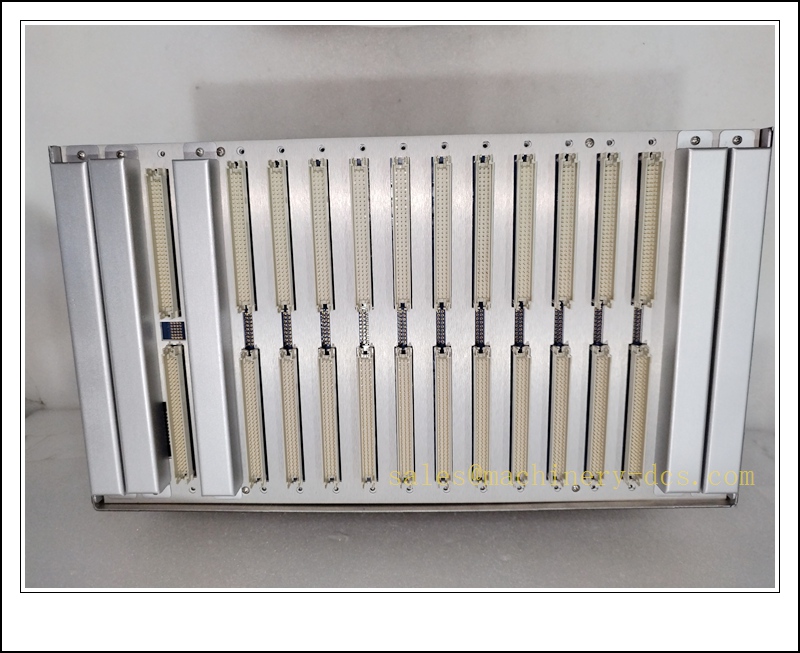
Bently Nevada 3500/05-01-01-00-00-00 System Rack and Backplane Assembly for 3500 Machinery Protection System
Product Description
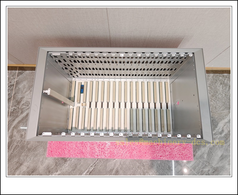
The 3500/05 is the mechanical chassis and proprietary backplane foundation of the Bently Nevada 3500 TSI machinery protection platform. The full part number 3500/05-01-01-00-00-00 defines a standard 13-slot rack assembly with integrated backplane, module guides, mounting hardware and rear wiring terminals. It provides shared power distribution, high-speed parallel backplane communication bus and mechanical housing for all 3500 series monitor, communication, keyphasor and power supply modules. This rack supports SIL-rated machinery protection configurations, hosting cards such as 3500/42 vibration monitors, 3500/22M Keyphasor and 3500/91 TDI/EGD gateways. It is engineered for continuous-duty deployment on steam turbines, gas turbines, compressors and generators in power, oil & gas and petrochemical facilities.
Technical Parameters
| Item | Specification |
|---|---|
| Manufacturer | Bently Nevada (Baker Hughes) |
| Model | 3500/05-01-01-00-00-00 |
| Function | 13-Slot System Rack with Integrated Proprietary Backplane |
| Host Platform | Bently Nevada 3500 Machinery Protection System |
| Slot Quantity | 13 total slots (accommodates power supply, monitors, comms modules) |
| Backplane Bus | 3500 proprietary parallel backplane for module data exchange |
| Mounting | Standard 19-inch rack-mount, panel mount compatible |
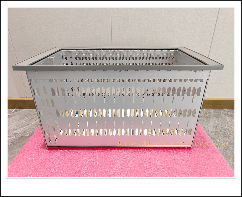
| Enclosure Material | Coated metal chassis, card guides, rear terminal hardware |
| Power Distribution | Distributes DC power from 3500/15 power supply to all installed modules |
| Operating Temperature | 0 °C ~ +60 °C |
| Storage Temperature | -40 °C ~ +85 °C |
| Humidity | 5%–95% non-condensing |
| Protection Rating | IP20 (must be installed inside control cabinet) |
| Suffix Definition | 01 = 13-slot rack; 01 = standard backplane; remaining 00 = no special options, no hazardous area modifications |
| Diagnostics | Backplane power rail status monitored by rack power supply and module firmware |
| Weight | Approx. 7.2 kg (empty rack, no modules) |
Recommended Related Models (8 units)
- 3500/42 SIL2-04-00: 4-channel proximitor/seismic machinery monitor
- 3500/91-01-01-01: TDI Transient Data Interface
- 161204-01: 3500/91 EGD Ethernet Gateway
- 3500/22M: Keyphasor speed & phase reference module
- 3500/50: Tachometer speed monitor
- 3500/15: Rack DC power supply module
- 3300 XL 8mm Proximity Probe: Shaft vibration transducer
- 100M2833: USB configuration service cable
3500/05-01-01-00-00-00
Compatibility & Installation Traps
Compatibility
- Primary host: Bently Nevada 3500 series monitor modules
- Supported modules: All standard 3500 full-height plug-in cards (3500/42, 3500/22M, 3500/91, 3500/50, 3500/15 etc.)
- Software: Bently Nevada 3500 Rack Configuration Software
- Note: Different 3500/05 suffix variants have different slot counts or backplane revisions. This 13-slot version cannot be mixed with 8-slot or other backplane revisions; older backplane hardware may have firmware compatibility limits with newer monitor modules.
Critical Installation Traps
- Backplane Revision Firmware Matching: Newer monitor modules may require a minimum backplane hardware revision. Mismatched revisions cause backplane handshake failures and modules to stay in fault state.
- Slot Function Rules: Slot 1 and 2 are reserved for power supplies for redundant configurations. Communication modules and monitor cards must follow defined slot assignments; arbitrary placement causes data communication failure.
- Torque for Rear Terminals: Over-tightening rear signal terminals can damage backplane PCB traces; loose terminals lead to intermittent transducer signal faults that are hard to reproduce on bench tests.
- Grounding and Shielding: The rack protective earth must be bonded to the plant instrument ground. Poor grounding creates ground loops, noise on proximity probe signals and spurious vibration alarms.
- ESD Risk During Module Swap: Backplane traces are exposed when modules are removed. Touching backplane connectors without ESD protection can damage the backplane or inserted modules.
- Cooling Airflow Requirement: The rack relies on cabinet forced or natural convection. Blocked ventilation, high cabinet ambient temperature triggers thermal faults in power supplies and monitors.
- Module Ejector Latches: Never force modules into slots. Bent ejector latches can damage edge connectors on the module and the backplane, resulting in intermittent power or communication loss.
- Rack Hot Swap of Power Rail: The empty backplane itself has no hot-swap capability for the main power bus. Removing the rack chassis while energized will drop power to all installed monitors and may initiate machinery protection trips.
Standard Operating Procedure (SOP)
- Pre-installation inspection: Inspect chassis, card guides, rear terminals and backplane edge connectors for bent pins, corrosion or burn damage. Verify full part number 3500/05-01-01-00-00-00.
- Configuration backup: Export the full rack configuration, channel settings, alarm thresholds and EGD/TDI parameters from the existing rack before migration.
- System preparation: Place all machinery protection loops into approved safety bypasses, notify control room and obtain the plant isolation work permit.
- Energy isolation: De-energize the 3500 rack power supply and apply lockout/tagout. Allow all module capacitors to fully discharge.
- Mechanical replacement: Remove all installed modules carefully, label each slot and wiring harness. Mount the new 3500/05 rack in the 19-inch cabinet, secure mounting fasteners, rewire all rear transducer and power terminals per site wiring drawings.
- Module re-installation: Insert power supply, monitor, Keyphasor and communication modules back into their original designated slots, fully engaging ejector latches.
- Power-up and self-test: Restore rack power. Observe front-panel module LEDs. Run rack-wide self-test via 3500 configuration software, confirm backplane communication between all cards.
- Loop and process qualification: Load saved rack configuration, validate transducer gap voltages, vibration/position readings, alarm trip logic and Ethernet/EGD data transmission. Remove safety bypasses only after all channels pass static and dynamic testing.
- Decommissioning: Label the old rack assembly with fault symptoms. Handle old backplane with ESD precautions.
3500/05-01-01-00-00-00
Application Scenarios
- Mechanical chassis and backplane backbone for Bently Nevada 3500 TSI machinery protection systems
- Hosting SIL2-rated vibration, thrust and speed monitoring modules for critical rotating equipment
- Power and backplane communication distribution for 3500/91 TDI waveform capture and EGD DCS gateway modules
- New project commissioning, rack replacement, cabinet retrofit and site migration of turbine/compressor supervision systems
- Preventive spare for backplane pin damage, chassis corrosion or ventilation failure
- Troubleshooting of intermittent backplane communication faults, shared power rail instability and rear terminal connection issues
- Power generation, oil & gas and petrochemical API 670 turbine supervisory instrument systems
Supporting Components
- ESD wrist strap, anti-static shielding bags and conductive work mat
- Torque screwdriver set for rear terminal blocks and rack mounting
- 3500/15 rack power supply modules (redundant pair optional)
- 3500/42, 3500/22M, 3500/91 spare monitor and communication modules
- 3300 XL proximity probes, extension cables and mounting hardware
- 100M2833 USB configuration cable and 3500 configuration software
- Shielded industrial Ethernet cable for TDI/EGD network
- Site wiring diagrams, safety bypass forms and SIL proof-test documentation

 Start Chat


 Send an Email


