
Description
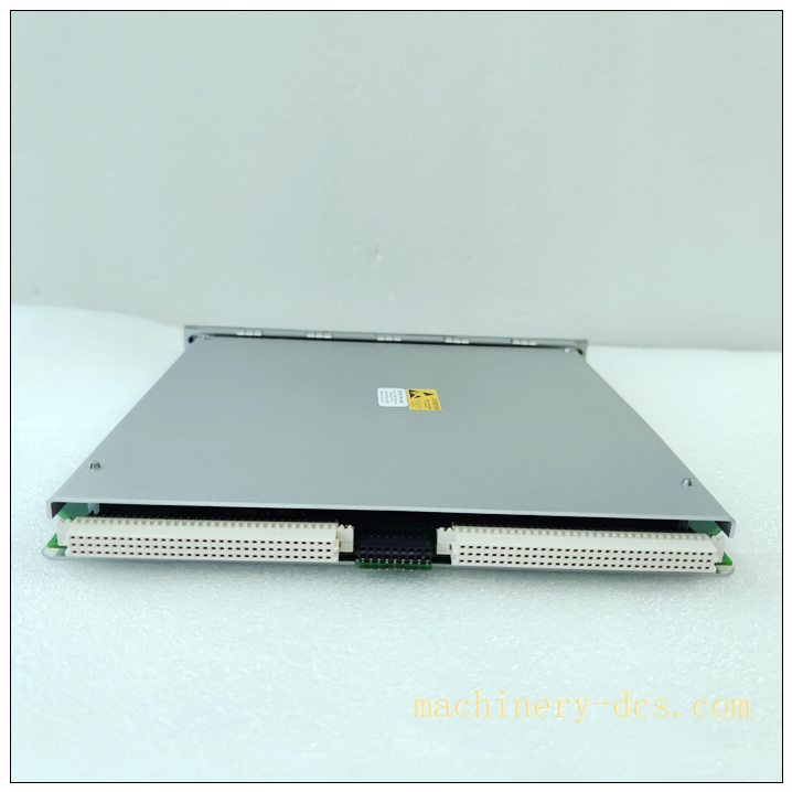
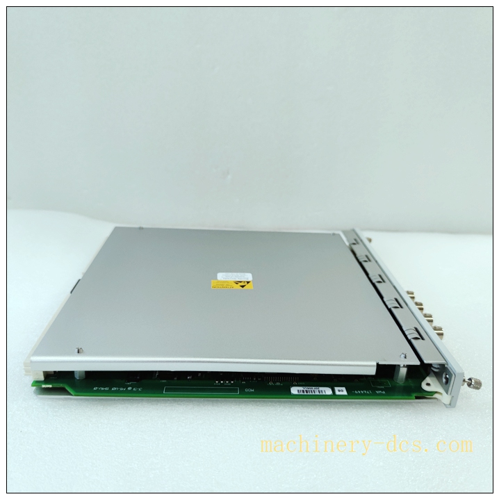
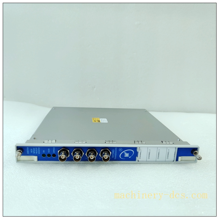
Bently Nevada 3500/77M‑03‑00 High‑Speed Shell Expansion Monitor Module
Product Detailed Information
The 3500/77M‑03‑00 is a dedicated shell expansion monitor module within the Bently Nevada 3500 machinery protection system. It monitors absolute thermal growth of turbine casing (shell expansion) by receiving position signals from LVDT shell expansion transducers. This module supports two independent LVDT input channels, provides real‑time casing thermal expansion measurement, configurable Alert / Danger alarm thresholds, Form‑C relay outputs, isolated 4‑20 mA analog outputs and comprehensive module self‑diagnostics. It plugs into standard slots of the 3500 rack backplane and supports hot‑swap under controlled plant operating conditions. Suffix‑03‑00 denotes standard hardware configuration without special factory options. OEM production is discontinued; NOS stock, calibrated refurbished and field‑recovered spare modules are widely applied for thermal‑power turbomachinery life‑extension maintenance.
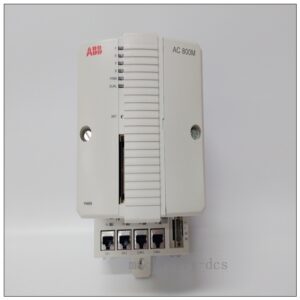
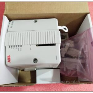
3500/77M-03-00 176449-09
Technical Parameters
| Item | Specification |
|---|---|
| Manufacturer | Bently Nevada (GE Vernova) |
| Model | 3500/77M‑03‑00 |
| Product Status | OEM Discontinued, spare‑part‑only supply |
| Measured Parameter | Turbine Shell (Casing) Absolute Thermal Expansion |
| Sensor Type | 2‑channel LVDT position transducer input |
| Measurement Range | User‑configurable, matches physical LVDT mechanical stroke; typical range ±25 mm / ±1.0 inch |
| Response Rate | High‑speed sampling for tracking fast thermal‑transient casing growth |
| Alarm Logic | Independent Alert (Alarm) & Danger (Trip) set‑points per channel; latching / non‑latching configurable |
| Relay Outputs | Form‑C dry‑contact relays for Alert, Danger, Module Fault; contact rating: 250 VAC / 30 VDC |
| Analog Output | Galvanically isolated 4‑20 mA per channel, proportional to measured expansion value; configurable fail‑safe output behavior |
| System Interface | 3500 rack backplane, intercommunicates with 3500/22M system processor, display unit and communication gateway |
| Power Supply | Power supplied entirely via 3500 rack power supply (3500/15) |
| Hot‑Swap | Supported under controlled plant conditions |
| Mounting | Slot‑mount inside Bently Nevada 3500 series rack chassis |
| Indicators | Front‑panel LED indicators: OK, Alert, Danger, Channel / Module Fault |
| Operating Temperature | 0 ℃ ~ +60 ℃ (indoor cabinet installation) |
| Storage Temperature | ‑40 ℃ ~ +85 ℃ |
| Humidity | 5‑95 % RH non‑condensing |
| Weight | ≈0.45 kg |
| Certifications | CE, UL, ATEX qualified; achieves SIL‑2 capability upon full system‑level assessment |
| Configuration Tool | 3500 System Configuration Software |
Compatibility & Installation Traps
Compatibility
- Bently Nevada 3500 rack chassis, 3500/15 power supply unit, 3500/22M system processor
- Matched‑stroke shell‑expansion LVDT field sensors for steam / gas turbine casing
- 3500/92 communication gateway for DCS / SCADA upper‑level host connection
- Official 3500 configuration software for parameter download and loop calibration
Critical note: 3500/77M‑03‑00 is exclusively for shell expansion measurement. It cannot substitute differential‑expansion module 3500/70M, vibration monitor 3500/42M or other monitor modules. Module firmware revision must align with 3500 rack system‑processor firmware; version mismatch triggers channel initialization failure or intermittent communication loss.
Installation Pitfalls
- LVDT stroke range mismatch: Configured measuring span must strictly match physical LVDT mechanical travel. Improper range setting results in clipped readings, false alarms or hidden measurement dead‑zones.
- LVDT wiring interference risk: LVDT signal cables shall be routed separately from high‑voltage power cables. Deploy Bently‑recommended shielded multi‑pair cables. Improper shielding or multi‑point grounding creates ground‑loops and drifting unstable readings.
- Hot‑swap safety limitation: Hardware supports hot‑swap, but removing the live module disables shell‑expansion protection function. For turbine safety loops, perform replacement during unit shutdown or stable reduced‑load operating conditions with proper protection bypass permit.
- Backplane slot constraint: Install only in valid monitor slots. Processor, power‑supply and gateway dedicated slots cannot accept 3500/77M module; wrong slot leads to module non‑detection.
- Inductive‑load relay damage risk: When relay contacts drive inductive field devices, external surge‑suppression components are mandatory. Without suppression, relay contacts will suffer premature erosion and burnout.
- ESD vulnerability: Backplane connector and internal signal circuits are static‑sensitive. ESD wrist‑strap and anti‑static mat are required for all handling activities; invisible ESD damage causes sporadic channel fault alarms without visible component damage.
- Part‑number suffix validation: Confirm full marking 3500/77M‑03‑00. Other suffix variants (‑01‑00,‑02‑00) carry different hardware options and cannot be directly drop‑in swapped without complete re‑configuration.
- Mandatory post‑swap calibration: After module replacement, re‑execute LVDT loop calibration, verify Alert / Danger threshold values, 4‑20 mA scaling and relay action logic. Factory default parameters do not retain turbine‑specific site settings.
Standard Operating Procedure (SOP)
- Pre‑work: Implement plant lock‑out‑tag‑out for turbomachinery protection rack. Evaluate turbine operating state; avoid hot‑swap during thermal‑transient or high‑load periods. Wear certified ESD anti‑static wrist strap.
- Data backup: Save complete 3500 system configuration file; record channel measuring range, Alert / Danger set‑points, 4‑20 mA scaling, relay latching mode and current firmware revision. Export historical fault event log.
- Module removal: Record front‑panel LED status before extraction. Release front‑panel latch handle, pull 3500/77M‑03‑00 module straight out of rack slot. Inspect 3500 backplane connector for bent pins, oxidation or contamination.
- Incoming inspection: Visually check spare module for mechanical damage to PCB and front‑panel hardware. Verify full part‑number marking and hardware / firmware revision.
- Mechanical mounting: Smoothly insert new 3500/77M‑03‑00 module into target rack slot; push firmly and close front‑panel latch to guarantee full backplane contact.
- Cabling: Reconnect field‑side LVDT sensor wiring on module front‑terminal block strictly following original drawings. Confirm cable‑shield termination implementation.
- Power‑on commissioning: Keep rack power energized. Wait for module boot‑up sequence. If firmware mismatch occurs, perform firmware upgrade / downgrade to match rack system‑processor version. Download backed‑up module configuration parameters.
- Functional validation: Confirm front‑panel OK LED remains steadily illuminated. Complete LVDT loop test to validate casing expansion reading. Simulate high‑value / low‑value input crossing thresholds, verify LED indication, relay‑contact actuation and 4‑20 mA output response. Confirm DCS‑side analog reading is consistent with rack display. Clear historical fault buffer and confirm no persistent module‑fault or channel‑fault alarms.
- Documentation: Update turbomachinery maintenance log, archive configuration file, firmware‑version and calibration‑test records. Properly package defective removed module. Release lock‑out‑tag‑out permit only after full acceptance‑test successfully completed.
3500/77M-03-00 176449-09
Application Scenarios
‑ Steam‑turbine / gas‑turbine casing shell‑expansion protection and continuous monitoring within thermal power plants ‑ Monitor absolute thermal growth of turbine casing, identify abnormal casing deformation risk ‑ Machinery protection interlock & DCS / SCADA condition‑monitoring integration ‑ Legacy Bently Nevada 3500 platform preventive maintenance & life‑extension retrofit projects
Matching & Supporting Components
- Bently Nevada 3500 rack chassis, 3500/15 power supply, 3500/22M system processor
- Shell‑expansion matched‑stroke LVDT position sensors and shielded field cables
- 3500 system configuration software; 3500/92 communication gateway for upper‑system interface
- ESD‑shielded anti‑static storage container for spare monitor‑module storage
Brand‑Related Alternative & Recommended Models
- 3500/77M‑01‑XX / 3500/77M‑02‑XX: Different suffix hardware variants; validate option‑code compatibility before substitution
- 3500/70M‑01‑00: Differential expansion monitor, different measurement function, cannot replace shell‑expansion module
- Bently Nevada System‑1 modern machinery‑monitoring platform: For complete system‑migration new‑build projects

 Start Chat


 Send an Email


