
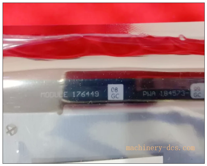
Description
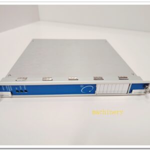
Bently Nevada 176449‑01 3500/40M Four‑Channel Proximitor Monitor Module
Meta‑Description
Bently Nevada 176449‑01 is the 3500/40M four‑channel proximitor monitor module for 3500 machinery protection rack. It accepts 3300‑XL proximity probe inputs for shaft radial vibration, thrust position, eccentricity and REBAM measurement, supports hot‑swap, dual‑alarm setpoints, fully API‑670 compliant for turbines, compressors and rotating equipment protection.
Product Core Overview
The 176449‑01 is the hardware part number for Bently Nevada 3500/40M Proximitor Monitor, a critical hot‑swappable monitoring module within the 3500 machinery protection system. Designed to interface with Bently Nevada 3300‑XL series proximity transducer systems, it converts probe gap signals into usable measurement values for rotating‑machinery protection and condition‑based diagnostics.
This 4‑channel module independently processes shaft relative vibration, thrust position, differential expansion, eccentricity and REBAM rolling‑element bearing motion data. Each channel supports user‑configurable Alert and Danger alarm thresholds. Powered via the 3500 rack backplane, it transmits measured data and alarm status to the system communication module for host‑system HMI display, event logging and relay output actions. Widely implemented across power generation, petrochemical and oil‑gas facilities to protect turbines, centrifugal compressors, pumps and generators against shaft‑related mechanical faults.
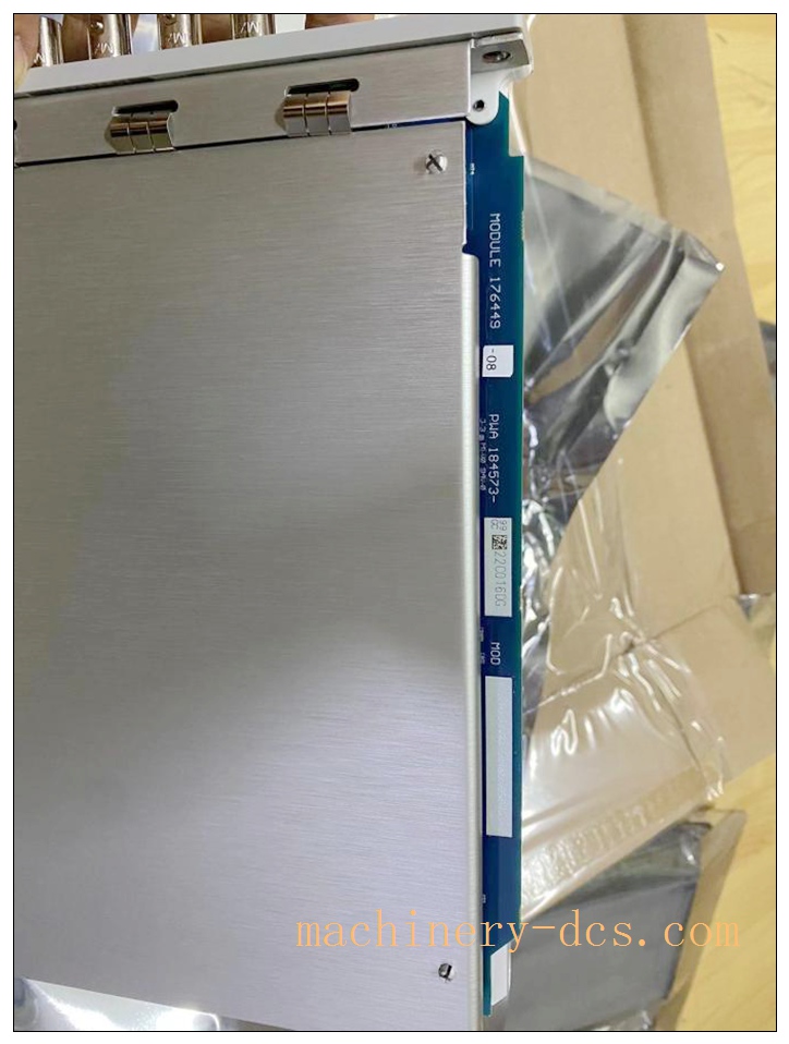
350040-01-00 176449-01
Main Technical Specifications
| Item | Parameter |
|---|---|
| Part Number | 176449‑01 (3500/40M) |
| Module Type | 4‑Channel Proximitor Monitor |
| Compatible System | Bently Nevada 3500 series rack‑based machinery protection system |
| Transducer Input | 3300‑XL proximity probe & proximitor systems |
| Supported Measurements | Radial Vibration, Thrust Position, Differential Expansion, Eccentricity, REBAM |
| Alarm Configuration | Two programmable setpoints per channel: Alert, Danger |
| Hot‑Swap Support | Yes, online replacement without rack power‑down |
| Power Supply | Backplane powered from 3500 rack power supply; typical 7.7 W consumption |
| Input Impedance | 10 kΩ (Standard I/O), 50 kΩ (TMR I/O) |
| Operating Temperature | 0 °C ~ +65 °C |
| Storage Temperature | −40 °C ~ +85 °C |
| Relative Humidity | 5 %‑95 % non‑condensing |
| Compliance | API‑670, CE, UL/cULus safety certifications |
| Communication | Backplane bus to 3500 system communication module |
| Installation | Standard 3500 rack slot mounting |
Note: Measurement range depends on the selected proximity probe model and total probe‑cable length.
Quality Control Procedures
- Visual & Mechanical Incoming Inspection: Each module undergoes visual inspection of PCB assembly, front‑panel hardware, connectors, labeling and serial‑number marking. Serial traceability is established for full‑lifecycle tracking.
- Backplane Interface Continuity Test: Verify rack‑backplane connector pin integrity, continuity and isolation performance.
- Channel‑by‑Channel Functional Calibration: Simulate proximity‑probe gap input signals to every channel; validate measurement accuracy, scaling output and sensitivity parameters against factory reference standards.
- Alarm Logic Validation: Inject simulated fault conditions to verify Alert / Danger threshold triggering, latch behaviour and alarm‑status reporting over system backplane bus.
- Communication Interface Test: Confirm reliable data exchange between monitor module and 3500 system communication module.
- Environmental Screening: Temperature cycling test simulates industrial operating range to verify stability under thermal stress.
- Electromagnetic Compatibility Screening: EMC interference test ensures correct operation in noisy industrial cabinet environments.
- Final Configuration & Document Archiving: Full‑function end‑of‑line validation. Test records are archived linked to unit serial number prior to factory release.
Related Brand Model Recommendations
- 176449‑02 (3500/42M): 4‑channel seismic/proximitor combined monitor, supports both proximity probes and 330400‑series accelerometers for mixed vibration monitoring.
- 176449‑09 (3500/70M): Velocity monitor module for velocity‑type seismic transducers.
- Matching Transducer Family: 3300‑XL proximity probes, 330100‑series proximitors, 330130 extension cables.
- System Accessory: 3500 system communication module, relay output modules, 3500 rack power supplies.
- Replacement Accessory: 128710‑01 recorder external termination block for signal buffering output.
Frequently Asked Questions (FAQ)
Q1: What transducers work with 176449‑01 (3500/40M)? A: It is exclusively designed for Bently Nevada 3300‑XL proximity probe‑proximitor systems. It cannot directly accept accelerometer or velocity‑sensor inputs; select 3500/42M for seismic sensor channels.
Q2: Does this module support hot‑swap? A: Yes. The 3500/40M supports hot‑swap. You can remove and replace the module while the 3500 rack remains powered. System configuration parameters are stored in rack non‑volatile memory, not on the module hardware.
Q3: Can I use 176449‑01 for casing acceleration vibration measurement? A: No. This proximitor monitor processes eddy‑current probe gap signals for shaft‑relative measurements. For casing acceleration, use 3500/42M monitor paired with 330400‑series accelerometers.
Q4: Where are alarm setpoints stored? A: Configuration and alarm setpoints are saved within the 3500 rack memory, not on the monitor hardware itself. Module replacement will not erase channel configuration.
Q5: What happens if total probe‑cable length does not match the proximitor nominal length? A: Measurement error and scaling drift will occur. Always use complete matched probe‑proximitor‑cable assemblies with correct nominal total length.
Q6: Can I repair the module on‑site? A: No. This is a sealed factory‑calibrated PCB assembly. Unauthorized opening voids certification and calibration status. Return faulty units to authorized service centre for repair or replacement.
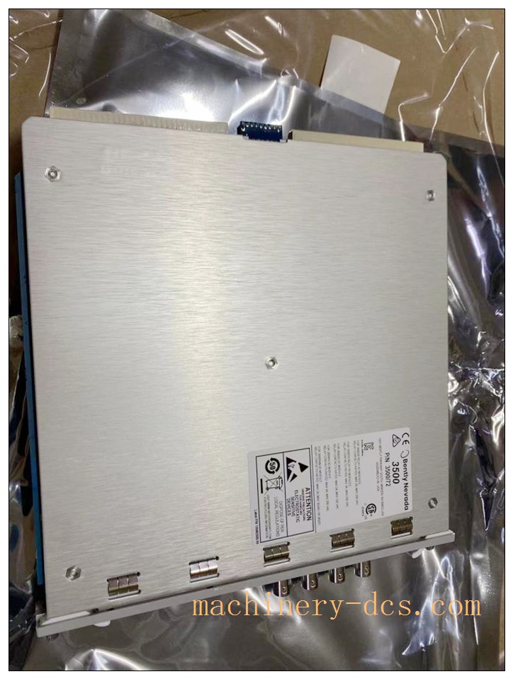
350040-01-00 176449-01
Installation & Configuration Guide
Pre‑Installation
- Inspect delivered module for physical transit damage. Confirm part number 176449‑01 and serial number match your order.
- Verify target 3500 rack slot is available, rack power supply and system communication module are functional.
- Prepare complete 3300‑XL proximity transducer assemblies (probe, proximitor, matched extension cable). Prepare external termination wiring for signal outputs and alarm relays.
- Review machinery protection drawings for measurement assignment, sensitivity and alarm setpoint values.
Mechanical Installation
- Insert 176449‑01 module into an available 3500 rack slot. Push firmly until backplane connector fully seats. Tighten front‑panel captive screws to secure module into rack.
Hot‑swap is allowed: rack may remain powered during insertion / removal.
Electrical Wiring
- Route proximitor signal wiring to corresponding external termination block. Follow site‑specific single‑point grounding rules to avoid ground‑loop noise.
- Confirm wiring assignment matches channel mapping defined in machinery protection drawing.
- Perform continuity and insulation resistance check before applying field transducer signals.
System Configuration & Commissioning
- Connect 3500 configuration software to the rack communication module.
- Open rack configuration, add “3500/40M” module to the corresponding slot position.
- Configure each channel: select measurement type, input transducer sensitivity, full‑scale range, Alert and Danger alarm setpoints, time‑delay parameters. Download configuration into the 3500 rack.
- Perform transducer gap‑check: adjust physical probe gap to operate within linear range of the 3300‑XL probe system. Verify live gap reading on HMI matches mechanical gap.
- Perform bump / shaft‑run‑out test to validate signal response. Confirm alarm logic functions as expected.
- Lock configuration and save configuration backup file before placing module into normal machinery‑protection operation.

 Start Chat


 Send an Email


