
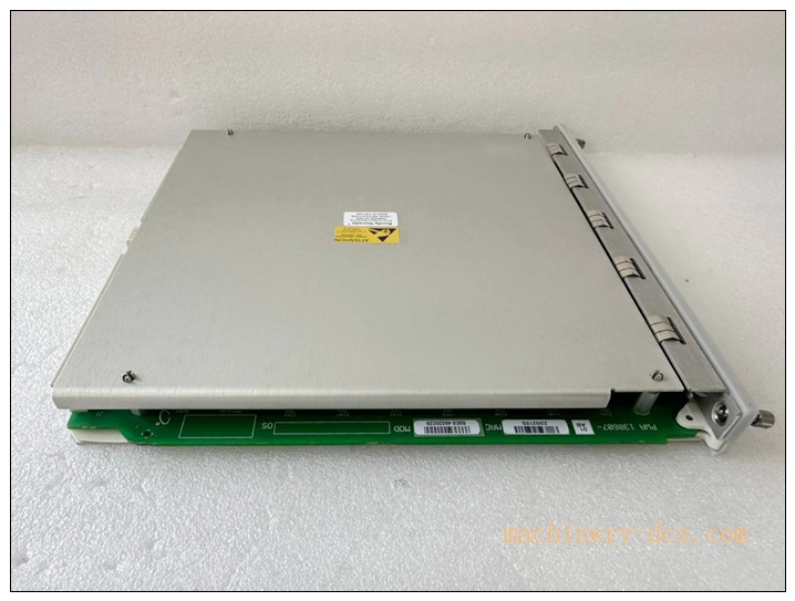
Description
Bently Nevada 138607‑01 Shielded Accelerometer Interconnect Cable Assembly
Meta‑Description
Bently Nevada 138607‑01 is a factory‑matched shielded interconnection cable for 330400‑series piezoelectric accelerometers. It features 3‑pin threaded connector termination, heavy‑duty shielding for EMC noise suppression, designed for harsh‑environment machinery vibration monitoring, compatible with Bently 330400 accelerometers and 3300 / 3500 monitor systems.
Product Core Overview
The 138607‑01 is an original factory‑matched signal cable assembly purpose‑built for Bently Nevada 330400‑series three‑wire piezoelectric accelerometers. Pre‑terminated with a 3‑pin threaded male connector on the sensor‑end and bare‑wired flying leads for monitor rack termination, this shielded cable maintains signal integrity for low‑level accelerometer vibration signals in electrically noisy industrial environments.
Double‑shielded construction minimizes electromagnetic interference and ground‑loop risks. It is engineered for continuous service inside power‑plants, refineries and compressor facilities, transmitting acceleration data from casing‑mounted accelerometers to 3300‑series and 3500‑series monitoring racks. Properly matched cabling preserves sensor factory calibration and frequency‑response performance of 330400 accelerometers; non‑approved third‑party cables may degrade measurement accuracy and high‑frequency bandwidth.
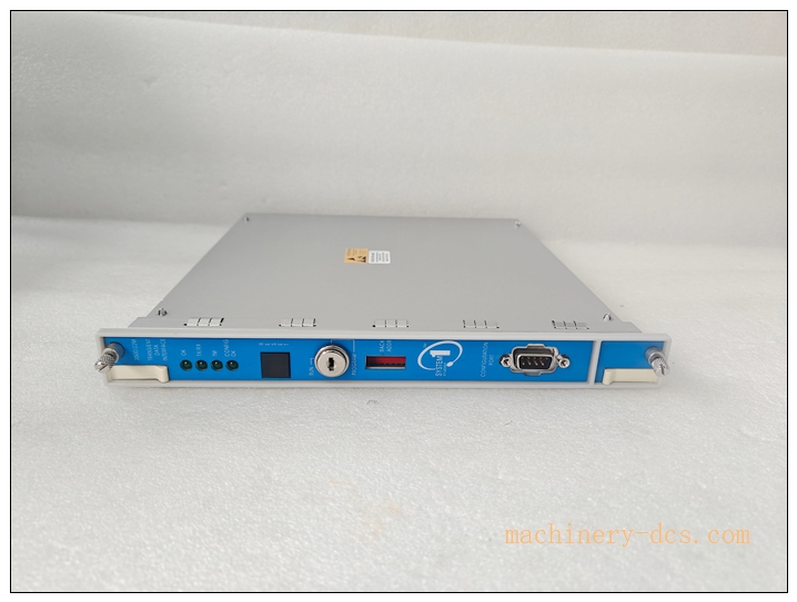
350022M 138607-01
Main Technical Specifications
| Item | Parameter |
|---|---|
| Part Number | 138607‑01 |
| Cable Type | Double‑shielded 3‑conductor instrumentation cable |
| Sensor‑End Connector | 3‑pin threaded male circular connector (mate with 330400‑series accelerometer female receptacle) |
| Monitor‑End Termination | Bare stripped flying leads |
| Conductor Count | 3 conductors (Signal,‑24 V DC Power, Common) |
| Shielding | Overall braided shield + inner foil shield, EMC optimized |
| Insulation Material | Industrial grade polymer, oil‑resistant |
| Operating Temperature | ‑55 °C ~ +125 °C |
| Cable Length | 1 meter (01 suffix = 1 m length variant) |
| Matched Sensor Family | 330400, 330425 piezoelectric accelerometers |
| Compatible Monitors | 3500/42, 3300/25, 3300/26 monitor modules |
| Max Recommended Total Run | 30 m when cascaded with approved extension cables |
| Application | Vibration signal transmission for casing accelerometers |
Quality Control Procedures
- Visual & Mechanical Inspection: Each finished cable assembly undergoes visual inspection of connector shell, threads, crimp joints, shielding braid and outer jacket. Connector mating threads are checked for damage.
- Continuity & Pin‑to‑Pin Test: 100 % continuity test for each conductor; verify open‑circuit and short‑circuit conditions between signal, power and shield paths.
- Insulation Resistance Test: High‑megohm insulation resistance measurement between conductors and shield to detect jacket or insulation defects.
- Connector Mating Validation: Physical mate‑demate cycling test with reference accelerometer connector to confirm locking‑ring engagement and mechanical fit.
- Shield Integrity Check: Verify shield continuity along full cable length for EMI suppression performance.
- Pull‑Strength Crimp Test: Sample pull‑test on crimp terminations to avoid loose internal connections under field vibration.
- Labeling & Traceability: Part number and length marking applied; batch‑traceability records archived before product release.
Related Brand Model Recommendations
- 138607‑02: Same cable construction, 2‑meter length.
- 138607‑05: Same cable construction, 5‑meter length.
- 130539: Standard multi‑purpose accelerometer cable, customizable cut‑to‑length, bare‑ends both sides.
- 16710: Armored heavy‑duty shielded cable for mechanically abusive installation sites.
- Matched Sensor: 330400‑02‑05‑00, 330425‑02‑05‑00 piezoelectric accelerometers
- Monitor Hardware: 3500/42 Accelerometer Monitor module, 3300/25 Peak Acceleration Monitor
Frequently Asked Questions (FAQ)
Q1: Which sensors does 138607‑01 work with? A: It is designed exclusively for Bently Nevada 330400‑series and 330425 three‑wire piezoelectric accelerometers. Not compatible with 3300‑XL proximity probe systems.
Q2: Can I splice or extend this cable on‑site? A: Field splicing is not recommended. Improper splices degrade shielding performance, introduce noise and may void sensor calibration validity. Use factory‑manufactured longer‑length variants instead.
Q3: What is the maximum allowable total cable length? A: Combined total cable run shall not exceed 30 meters for 330400‑series accelerometers. Longer runs degrade high‑frequency response and signal‑to‑noise ratio.
Q4: How should I handle the cable shield at the monitor end? A: Terminate cable shield only at the monitor‑system grounding terminal following site drawing requirements. Avoid multi‑point grounding to prevent ground‑loop noise. Do not connect shield to sensor housing.
Q5: Can I use this cable in hazardous‑area installations? A: Verify cable approvals match local site hazardous‑zone classification. Follow national explosion‑proof wiring codes when deployed with CSA‑certified accelerometers.
Q6: Can I repair a damaged cable assembly? A: No. Damaged shielding, cracked jacket or deformed connector pins require full cable assembly replacement. Field repair compromises EMC performance.
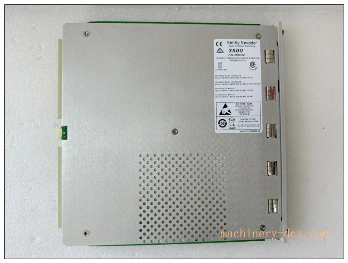
350022M 138607-01
Installation & Configuration Guide
Pre‑Installation
- Inspect cable assembly upon receipt. Confirm part number 138607‑01 and length 1 meter, check connector threads, outer jacket for cuts, cracks or transportation damage.
- Confirm compatibility with target accelerometer (330400 / 330425 series) and monitor module (3500/42 or 3300‑series).
- Plan cable routing: Route away from high‑power motor cables, VFD drives and heavy‑current power wiring to minimize electromagnetic noise pickup. Allow slack for machine thermal expansion and vibration movement; avoid sharp‑bend stress points.
Mechanical Installation
- Align the 3‑pin male connector with the mating female receptacle on the accelerometer. Hand‑tighten the threaded locking ring only. Do not use tools to over‑torque the connector.
- Secure cable run with cable clamps. Do not hang the full cable weight from the sensor connector. Eliminate tensile stress, sharp bending or twisting force transferred to sensor housing. Maintain minimum cable bend radius ≥ 10× cable outer diameter.
Electrical Wiring at Monitor Rack
- Strip flying‑lead ends per rack terminal block requirements.
- Terminal assignment:
- Conductor A → Signal input
- Conductor B → −24 V DC power supply
- Conductor C → Common / Return
- Cable shield → System shield terminal (single‑point grounding only)
- Confirm no short‑circuit between signal‑power‑shield before power‑up. Avoid multi‑ground loops.
Commissioning Check
- Power‑up monitoring rack. Read channel DC bias voltage to confirm accelerometer receives proper‑24 V DC supply.
- Perform tap / bump test: tap the accelerometer housing, observe real‑time vibration readings on monitor HMI. Confirm responsive, noise‑free signal.
- Verify alarm and warning threshold settings are configured per machinery protection drawing.

 Start Chat


 Send an Email


