
Description
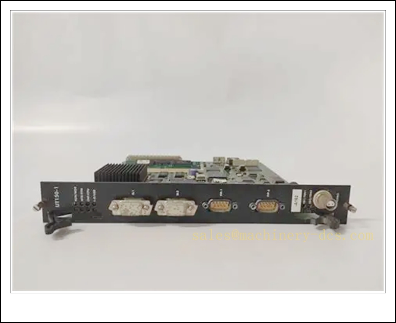
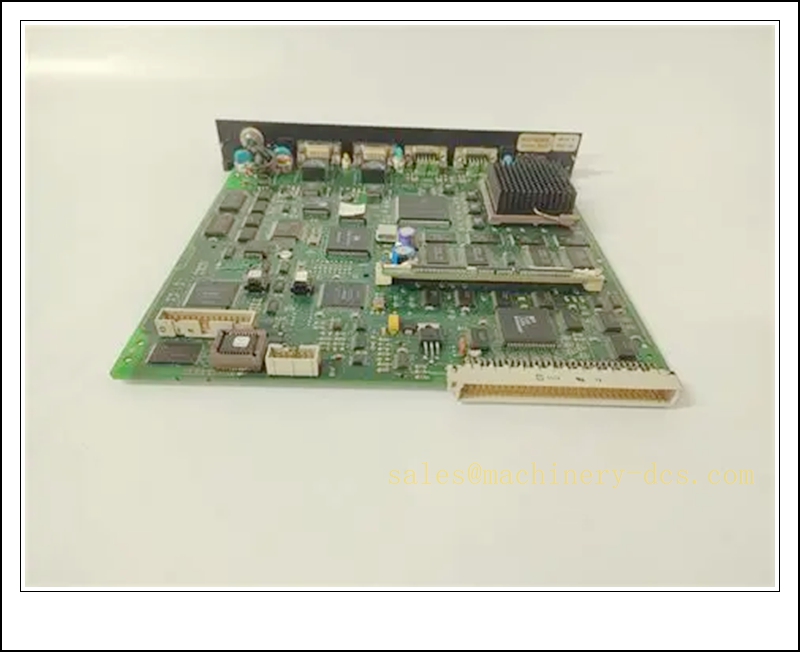
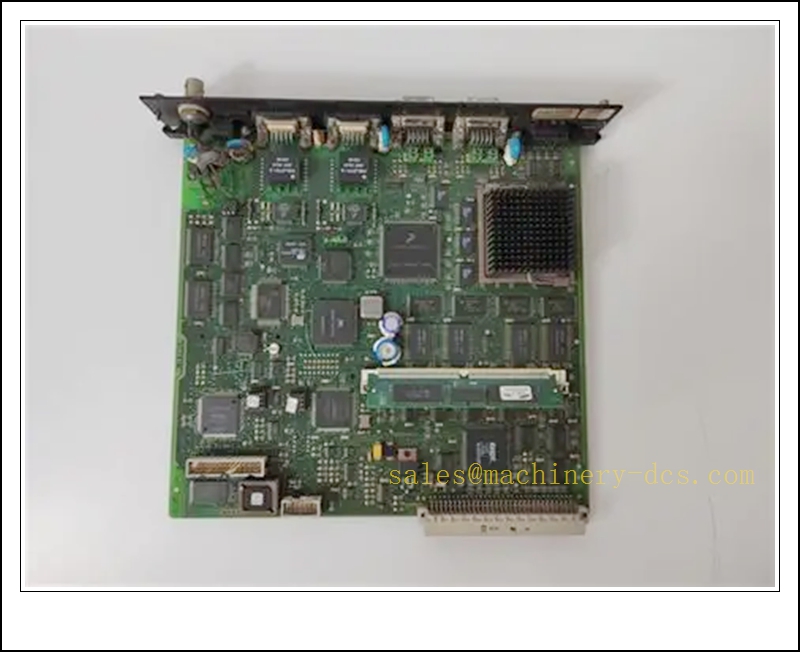
ALSTOM UT150-2 (KWZ6018990P0457) WorldFIP Network Coupler & Local I/O Processor Module, Alspa CE2000/CE3000 DCS System
Product Description
The UT150-2, part number KWZ6018990P0457, is a rack-mounted network coupler and local processing module designed for the legacy Alstom Alspa CE2000 / CE3000 distributed control system. It acts as the bridge between the main controller rack and the F8000 WorldFIP fieldbus network operating at 2.5 Mbps over copper media. Built around a Motorola 68040 33 MHz microprocessor, the module performs three core roles: WorldFIP bus coupling, management of up to 16 local I/O sub-modules, and execution of standalone local control logic. It supports real-time data exchange between field devices and the DCS host, handles field diagnostics, and stores process parameters. This unit is a critical obsolete spare for power generation, turbine and industrial process control retrofits and maintenance.
Technical Parameters
| Item | Specification |
|---|---|
| Manufacturer | ALSTOM (legacy Alspa DCS line) |
| Model | UT150-2, Code: KWZ6018990P0457 |
| Function | WorldFIP 2.5Mbps Coupler + Local I/O & Control Processor |
| CPU | Motorola 68040, 33 MHz |
| Fieldbus | WorldFIP, copper medium, 2.5 Mbps |
| I/O Capacity | Manages up to 16 local I/O modules |
| Power Supply | 5 VDC backplane rack supply; auxiliary isolated logic rails |
| Form Factor | Standard Alspa CE rack plug-in module |
| Dimensions | 265 × 36 × 265 mm |
| Weight | Approx. 0.60 kg |
| Diagnostics | Bus error counter, watchdog supervision, I/O channel fault logging, memory parity check |
| Operating Temperature | 0 °C ~ +55 °C |
| Storage Temperature | -40 °C ~ +85 °C |
| Protection | IP20 (for cabinet mounting) |
| Compliance | CE, EMC for power station industrial environments |
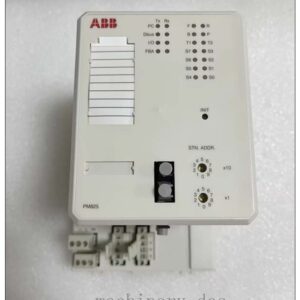
| Status Indicator | LEDs for rack power, WorldFIP link active, local run state, watchdog / fault alarm |
Recommended Related Models (8)
- C0202450: Alternate Alstom part code for UT150-2
- UT150-1: Earlier generation WorldFIP coupler for Alspa CE series
- CE2000 CPU Module: Main rack controller paired with UT150-2
- F8000 WorldFIP Fieldbus Interface: Field-side network adapter
- Alspa CE2000 Analog Input Module: 4–20mA I/O card managed by UT150-2
- Alspa CE2000 Digital Output Module: Discrete relay output sub-card
- CE3000 Power Supply Rack Unit: Rack power for Alspa CE chassis
- WorldFIP Bus Terminator: Copper line termination resistor for FIP network
Compatibility & Installation Traps
Compatibility
- Primary host systems: ALSTOM Alspa CE2000 and CE3000 DCS racks
- Network: WorldFIP copper-based 2.5 Mbps fieldbus
- Field devices: F8000 remote I/O stations, analog/digital sub-modules in the Alspa range
- Note: This is a proprietary legacy Alspa DCS module; it cannot be substituted with generic Modbus, Profibus or standard PLC CPU cards.
Critical Installation Traps
- Firmware Version Lock: The firmware must match the existing /CE3000 rack software revision. Mismatched firmware causes WorldFIP link failure, loss of remote I/O or unexpected control state jumps. Always confirm firmware version before ordering.
- WorldFIP Termination Rules: The copper WorldFIP bus requires proper line terminators at both physical ends. Missing or duplicate termination leads to bus reflections, intermittent communication dropout that worsens with temperature swings.
- Backplane Keying & Pin Integrity: The module uses rack keying. Forcing insertion with misaligned pins will damage the backplane connector and create intermittent I/O or bus faults which are hard to reproduce on bench testing.
- ESD Sensitivity: The 68040 processor and bus transceiver circuits are ESD-sensitive. All handling and replacement must take place inside an ESD-controlled cabinet workstation with grounded wrist strap.
- Rack Airflow & Heat Derating: The module relies on rack forced cooling. Blocked fan filters or over-temperature operation trigger watchdog resets and bus disconnects. Do not operate above rated 55 °C ambient.
- Isolation of Fieldbus Wiring: WorldFIP copper cable must be routed separately from high-power AC/DC drive cables. Common-mode noise can corrupt FIP telegrams and cause random loss of remote stations. Use shielded twisted pair with single-point earth.
- Memory and Parameter Backup: Local control logic and calibration values are stored onboard. Module replacement erases local parameters; offline backup of configuration is mandatory before swap-out.
- Hot Swap Limitations: Verify rack specifications before hot removal. Some configurations do not support hot swapping of the , and removal can trigger ESD trips or control hold.
Standard Operating Procedure (SOP)
- Pre-installation inspection: Examine the PCB, edge connector and front panel for corrosion or physical damage. Cross-check part number KWZ6018990P0457 against the DCS spare list and confirm firmware revision.
- Configuration backup: Upload and save the local control logic, I/O mapping and WorldFIP network parameters from the existing to the engineering station.
- Energy isolation: Place affected control loops into manual / hold state. If hot swap is not approved, shut down the rack auxiliary power and apply lockout/tagout.
- Mechanical replacement: Release the module ejector levers, extract the old unit. Insert the replacement fully into the assigned rack slot and close latches to seat the backplane connector.
- Power-up and self-test: Restore rack power. Observe front panel LEDs; confirm rack power, run status and WorldFIP link indicators activate. Execute onboard memory and watchdog diagnostics from the engineering tool.
- Network and I/O validation: Download the saved configuration to the new module. Verify WorldFIP bus traffic, remote F8000 stations and all 16 attached local I/O modules are detected without channel faults.
- Process qualification: Return control loops to auto mode gradually. Monitor bus health, I/O refresh rate and alarm behaviour for thermal and load transients before returning the system to full production.
- Decommissioning: If removing the faulty unit, pack it in anti-static shielding bags. Label with fault symptoms for failure analysis.
Application Scenarios
- WorldFIP fieldbus coupling for Alstom Alspa / CE3000 DCS in power generation plants
- Local discrete and analog I/O management for turbine auxiliary control, boiler and balance-of-plant systems
- Execution of independent local control logic when the main DCS host communication is interrupted
- Preventive maintenance and spare stocking for legacy Alspa DCS retrofits
- Troubleshooting intermittent WorldFIP bus faults, remote I/O dropout and watchdog reset events
- Power station DCS lifecycle extension and obsolescence replacement projects
- Engineering validation of F8000 remote I/O network topology and bus load testing
Supporting Components
- ESD wrist strap, anti-static shielding bags and conductive work mat
- Rack ejector tool and torque screwdriver for module latches
- WorldFIP shielded twisted-pair fieldbus cable and approved terminators
- Alspa / engineering software and communication dongle
- Rack fan filter replacement set for cabinet airflow maintenance
- Spare CE rack backplane connector repair kit
- CE series rack regulated power supply unit
- F8000 remote I/O station assemblies

 Start Chat


 Send an Email


