
Description
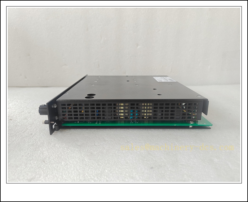
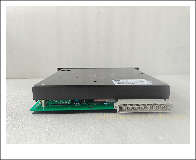
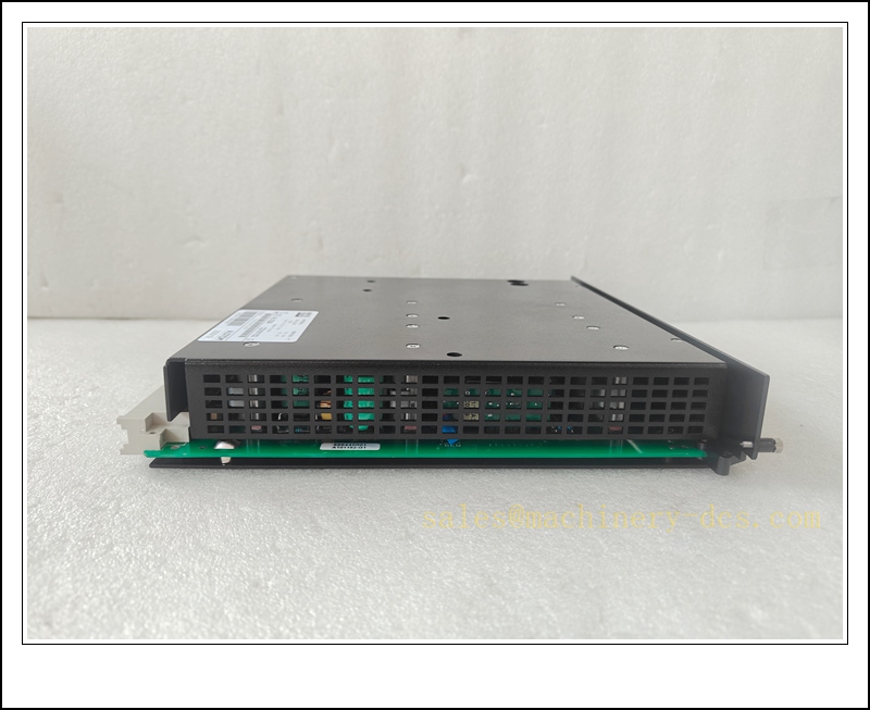
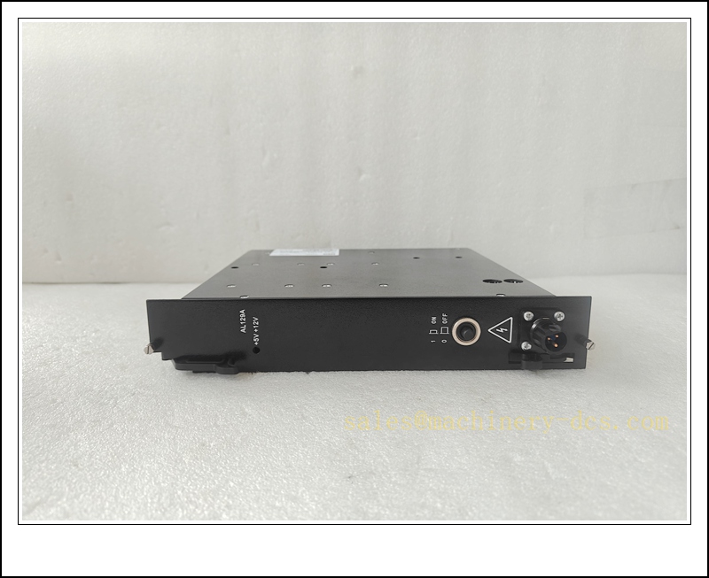
ALSTOM AL129A-CD10152 Isolated Chopper AC/DC Rack Power Supply Module, Alspa CE2000 / CE3000 DCS System
Product Description
The AL129A-CD10152 is a rack-mounted isolated switching chopper power supply developed by Alstom for the legacy Alspa CE2000 and CE3000 distributed control system. It converts wide-range AC mains input into galvanically isolated, regulated +5VDC and +12VDC rails to power rack CPU, WorldFIP bus couplers such as UT150-1 / UT150-2, local I/O modules and backplane logic circuits. Built for high-reliability power generation environments, it incorporates overvoltage, overcurrent and over-temperature protection. This is an obsolete, end-of-life spare critical for boiler, turbine and balance-of-plant control rack maintenance and lifecycle extension in power stations.
Technical Parameters
| Item | Specification |
|---|---|
| Manufacturer | ALSTOM (later GE Vernova power conversion) |
| Model | AL129A-CD10152 |
| Function | Rack AC/DC Chopper Power Supply, Isolated Dual DC Output |
| Input | 96–253 VAC, 50/60Hz wide range |
| Output | +5VDC @10A; +12VDC @4A, total rated 120W |
| Isolation | Galvanic isolation between AC input and DC output |
| Switching Topology | High-frequency chopper converter |
| Protection | Overvoltage, overcurrent, over-temperature shutdown with latch |
| Form Factor | Alspa CE rack plug-in module for AM163/AM164/AM166 chassis |
| Mounting | FB178 series rack backplane |
| Operating Temperature | -20 ℃ ~ +60 ℃ |
| Storage Temperature | -40 ℃ ~ +85 ℃ |
| Protection Class | IP20 (cabinet internal use only) |
| Compliance | CE, EMC for power station industrial environments |
| Weight | Approx. 0.75 kg |
| Status Indicator | Front panel LED for main power OK, fault alarm |
Recommended Related Models (8 units)
- AL129A-CD101152: Alternate revision of the same AL129A power supply
- UT150-1 KWZ6029068P0157: WorldFIP 1Mbps coupler processor for CE rack
- UT150-2 KWZ6018990P0457: WorldFIP 2.5Mbps coupler processor
- CE2000 Main CPU Module: Rack host controller powered by AL129A
- Alspa CE Analog Input Module: 4–20mA field I/O card
- Alspa CE Digital Output Module: Discrete control I/O card
- FB178 Backplane: Chassis backplane for Alspa CE racks
- WorldFIP Bus Terminator: Termination resistor for fieldbus network
ALSTOM AL129A-CD10152
Compatibility & Installation Traps
Compatibility
- Primary host systems: ALSTOM Alspa CE2000 and CE3000 DCS rack chassis
- Load devices: CE rack CPU, UT150 series WorldFIP couplers, local I/O cards
- Note: Proprietary rack power module; cannot be substituted with generic DIN-rail power supplies. variants are not fully cross-revision compatible without rack configuration verification.
Critical Installation Traps
- Revision Matching: CD10152 variant pinout and backplane signal definition differ slightly from CD101152. Mismatched revision may cause rail sequencing faults, power cycling or intermittent module resets. Confirm part code before replacement.
- Rack Redundancy Sequencing: In redundant dual rack configurations, power-up sequencing must follow site procedure. Uncontrolled hot insertion may trigger backplane voltage transients and crash active control CPU.
- Backplane Connector Integrity: Bent pins on the edge connector produce unstable supply rails, random watchdog resets and WorldFIP communication dropout that are hard to reproduce on bench testing.
- High ESD Sensitivity: The chopper control PCB and secondary regulation circuits are ESD-sensitive. All service must be performed on a grounded ESD workstation with wrist strap.
- Cooling Airflow Requirement: The module depends on rack forced convection. Blocked fan filters or cabinet over-temperature activate thermal shutdown and drop the entire rack control bus.
- AC Input Wiring Polarity & Earth: Mains protective earth must be securely terminated. Poor earthing increases common-mode noise on WorldFIP fieldbus and causes remote I/O dropouts.
- Load Pre-Check Before Power-Up: Short-circuit on the backplane or a faulty I/O card will immediately trigger current-limit latch-off. Isolate all load modules if a repeated fault occurs.
- Hot Swap Limitation: Not all CE2000 rack versions support hot swap of the rack main power supply. Unauthorized live removal leads to full rack power loss and control trip.
Standard Operating Procedure (SOP)
- Pre-installation inspection: Examine module housing, edge connector and internal PCB for burn marks or corrosion. Verify full part number -CD10152 against the rack spare list.
- System preparation: Put all turbine/boiler control loops into manual or hold state. For non-redundant racks, confirm plant permit for rack power isolation.
- Energy isolation: Disconnect the AC mains feed to the rack, apply lockout/tagout. Allow capacitors inside the old power supply to fully discharge.
- Mechanical replacement: Operate ejector latches and extract the faulty . Insert the replacement unit fully into the designated rack slot and engage latches to seat the backplane connector.
- Power-up and self-test: Restore AC input power. Observe front panel power and fault LEDs. Measure +5V and +12V rail voltages at the backplane test points to confirm tolerance.
- Rack module validation: Power on remaining rack CPU, UT150 coupler and I/O modules. Confirm WorldFIP bus link, remote F8000 stations and local I/O channels are online without fault codes.
- Process qualification: Gradually return critical control loops to automatic mode. Monitor rail stability, bus load and alarm behavior through thermal and load transients before releasing to full plant operation.
- Decommissioning: Ensure full capacitor discharge before handling the faulty unit. Pack in anti-static shielding bags and label with fault symptoms for failure analysis.
Application Scenarios
- Isolated regulated DC power feed for Alspa CE2000 / CE3000 DCS control racks
- Powering WorldFIP couplers, rack CPU and local analog / digital I/O modules
- Turbine auxiliary control, boiler and balance-of-plant control in thermal and hydro power plants
- Preventive maintenance and spare inventory stocking for obsolete Alspa DCS platforms
- Troubleshooting of random rack resets, WorldFIP bus instability and unexplained I/O channel dropout
- Power station DCS obsolescence retrofit and rack life extension projects
- Redundant power architecture commissioning for high-availability turbine protection systems
Supporting Components
- ESD wrist strap, anti-static shielding bags and conductive work mat
- Rack ejector levers and torque screwdriver set
- AC input mains cable and certified protective earth terminal blocks
- Alspa CE rack fan and filter replacement kit
- FB178 rack backplane repair kit and spare edge contacts
- Alspa /CE3000 engineering software and communication dongle
- Digital multimeter for DC rail voltage verification
- F8000 WorldFIP remote I/O station assemblies

 Start Chat


 Send an Email


