
Description
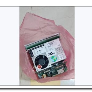
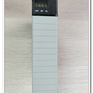
ABB LTC745A101 Crowbar Trigger Board, Part No. 3BHE039905R0101
Official Product Title: ABB LTC745A101 Crowbar Trigger Board, Part No. 3BHE039905R0101
Brand: ABB
Model: LTC745A101
Material Number: 3BHE039905R0101
Product Series: ABB High‑Power Drive Protection Board Series
Country of Origin: Switzerland
Product Type: Plug‑in Crowbar Protection / Thyristor Trigger Circuit Board
Product Core Overview
The ABB LTC745A101 (3BHE039905R0101) is a dedicated plug‑in crowbar trigger board for ABB medium‑to‑high‑power variable‑speed drive systems. Its core function is DC‑link overvoltage protection: when dangerous over‑voltage occurs on the DC bus caused by motor regeneration energy, load transients or grid disturbances, the board sends trigger pulses to activate the crowbar thyristor, shorting excess energy and protecting inverters and power semiconductors from voltage breakdown damage.
Equipped with on‑board voltage sensing circuit, thyristor pulse‑trigger unit, status monitoring and fault feedback logic, this board plugs directly into the drive power rack backplane. It provides real‑time over‑voltage detection, fast trigger response and diagnostic signal feedback to main drive controller. Widely deployed for heavy‑duty industrial drives in metallurgy, mining hoists and large‑scale pumping equipment, it supports new‑build installation and legacy ABB drive spare‑part replacement projects.
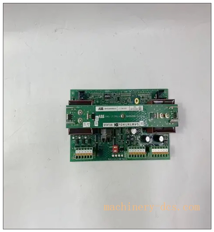
3BHE039905R0101 LTC745A101
Main Technical Specifications
| Parameter | Specification |
|---|---|
| Manufacturer | ABB |
| Model | LTC745A101 |
| Material Code | 3BHE039905R0101 |
| Board Function | DC‑Link Crowbar Over‑Voltage Protection & Thyristor Trigger |
| DC Bus Working Range | 600 Vdc ~ 1200 Vdc (matched to high‑power drive stack) |
| Control Supply | 15 Vdc ±10 % auxiliary control power |
| Trigger Output | Isolated pulse output for crowbar thyristor firing |
| Response Time | Microsecond‑level trigger upon over‑voltage threshold crossing |
| Monitoring Signal | Status / fault feedback signal to main drive controller |
| Operating Temperature | −20 °C ~ +60 °C |
| Storage Temperature | −40 °C ~ +85 °C |
| Mounting | Plug‑in slot‑mount inside ABB high‑power drive rack |
| Protection Degree | IP20 (cabinet‑only installation) |
| Weight | 0.32 kg |
| Dimension | 126 mm × 124 mm × 22 mm |
| Certification | CE, RoHS compliant |
| Warranty | 12‑month manufacturer warranty |
ABB Related Drive Protection Board Series Recommended Models (6+)
- LTC745A101 (3BHE039905R0101): Standard crowbar trigger board for high‑power drive DC‑link over‑voltage protection (reference model)
- LTC746A101: Enhanced crowbar board with extended voltage detection range for higher‑voltage drive stacks
- LTC747A101: Dual‑channel crowbar trigger board for redundant protection configuration
- 3BHE024885R0101: Drive interface monitoring board, collects multi‑group power‑unit status signals
- 3BHE022287R0101: Gate drive pulse board for high‑power IGBT power unit triggering
- 3BHE034570R0101: DC‑bus voltage & current sensing measurement board
- 3BHE025541R0101: Auxiliary power supply board for internal drive control circuits
Professional Quality Control & Test Standard Operating Procedure (SOP)
- Incoming Component Inspection Inspect high‑voltage sensing resistors, pulse‑transformer assemblies, optocouplers, PCB substrate and backplane connectors. Verify all components comply with ABB high‑voltage power‑board component specifications. Reject non‑conforming parts before assembly.
- PCB Assembly & Bench Functional Test After SMT and soldering assembly, perform power‑on bench test. Inject simulated DC‑bus over‑voltage signals to verify threshold detection accuracy, thyristor trigger pulse output waveform, fault‑status feedback signal output. Check for short‑circuit and leakage‑current risks on high‑voltage circuits.
- Thermal Burn‑in Aging Test 72‑hour powered aging test at 55 °C ambient temperature. Apply cyclic simulated over‑voltage trigger events continuously. Monitor board temperature rise, trigger‑pulse stability and status‑signal output, screen early‑failure hardware defects.
- Environmental Compliance Validation Conduct temperature cycling, mechanical vibration‑shock test and EMC EMI/EMS testing following IEC 61000‑6‑2 and IEC 60068 standards, simulate heavy‑industry cabinet harsh interference environment.
- Full‑System Drive Rack Integration Test Insert LTC745A101 into matching high‑power drive rack. Test backplane interface interaction with main drive controller, real‑time DC‑bus voltage sampling, crowbar trigger action, fault‑alarm reporting and drive‑system interlock response.
- Final Calibration & Batch Sampling Release Calibrate over‑voltage detection threshold parameters. 5 % random‑sample retest per production batch. Generate traceable factory‑test records before labelling and shipment.
New Module Installation Guidelines
Important Safety Note: This board works together with high‑voltage DC‑bus circuits. Strictly cut off main power and implement DC‑bus discharge before any installation work to avoid electric shock hazard.
6.1 Pre‑installation Preparation
Fully power‑down the whole drive system and confirm DC‑bus capacitors are completely discharged. Wear anti‑static wristband for ESD protection. Inspect for PCB damage, burnt traces, bent pins or connector corrosion. Prepare insulated screwdriver; record original jumper / DIP‑switch positions of old board for reference.
6.2 Hardware Rack Installation
Open drive cabinet power‑electronics protective cover. Align with rack slot guides, insert horizontally and push firmly until backplane connector is fully seated. Fasten front‑panel locking screws. Re‑set jumpers and DIP‑switches exactly same as original reference board. Reconnect trigger pulse wiring and status‑signal terminals; tighten terminals with specified torque value, strictly follow official wiring diagram. Keep high‑power cables separated from signal wiring to reduce EMI interference.
6.3 System Configuration & Commissioning
Restore drive‑system auxiliary control power. Enter ABB drive engineering tool. Confirm controller recognizes hardware. Verify over‑voltage protection threshold parameters match equipment design value. Perform simulated over‑voltage trigger test under no‑load condition, check crowbar trigger action and corresponding fault alarm feedback. Save drive‑parameter backup files offline.
6.4 Post‑installation Validation
Check drive controller fault‑diagnosis status; confirm no hardware fault alarms. Run 4‑hour no‑load and partial‑load continuous test. Monitor DC‑bus voltage sampling value and board status feedback signal. Confirm no false triggering or abnormal fault reports, complete commissioning acceptance.
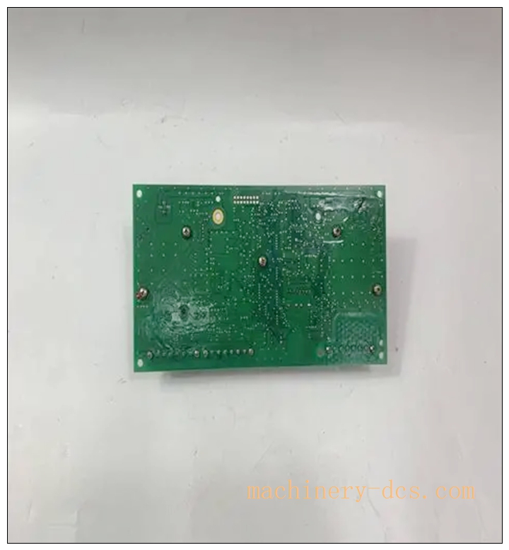
3BHE039905R0101 LTC745A101
Application Scenarios & Product Features
Application Scenarios
- ABB medium‑high‑power industrial variable‑frequency drive systems
- Metallurgical rolling‑mill main‑drive equipment with heavy regenerative load
- Mine hoist and lifting equipment drive protection
- Large‑capacity pump & fan drive with frequent dynamic load fluctuation
- Industrial heavy‑duty variable‑speed equipment facing regenerative energy risks
- Legacy ABB high‑power drive system spare‑part replacement & retrofit projects
Core Features
- Fast microsecond‑level DC‑link over‑voltage detection and crowbar thyristor trigger protection
- Integrated voltage‑sensing circuit, trigger‑pulse generation and fault‑status feedback
- Standard plug‑in rack‑mount structure, convenient for on‑site replacement and maintenance
- Industrial‑grade high‑voltage component design, adapting to heavy‑industry cabinet environment
- Provides fault‑diagnosis feedback signal for main drive controller to record protection events
- Strictly matched with ABB high‑power drive stack hardware architecture
- Supports protection action recording for post‑fault analysis
Frequently Asked Questions (FAQ)
Q1: Drive reports “crowbar board fault” alarm immediately after power‑on
A1: Confirm auxiliary 15 Vdc control supply is within rated range. Check whether is fully inserted into rack slot and locking screws are tightened. Verify jumper and DIP‑switch settings match system requirements. Perform full drive power‑cycle; if alarm persists return board for hardware inspection.
Q2: Crowbar falsely triggers during normal drive operation
A2: Check DC‑bus voltage sampling circuit; inspect interference from surrounding high‑power wiring. Verify over‑voltage threshold parameter setting conforms to drive‑system design. Check cabinet ambient temperature stays within rated range. Inspect for aging or drift of high‑voltage sampling components.
Q3: No crowbar trigger action when DC‑bus over‑voltage occurs
A3: Check auxiliary control‑power supply of . Verify jumper configuration and trigger‑pulse output wiring connection. Confirm drive‑controller protection‑parameter is enabled. Inspect crowbar thyristor unit and pulse‑output loop for open‑circuit fault.
Q4: Can substitute for other ABB crowbar board models?
A4: Only applicable for matched designated high‑power drive rack models. Cannot be directly used for non‑matching drive hardware; incorrect substitution may cause protection failure or equipment damage.
Q5: Drive reports inconsistent DC‑bus voltage reading
A5: Check wiring connection between and DC‑bus sampling point. Check for high‑frequency electromagnetic interference on signal loop. Verify no dust accumulation on high‑voltage sampling circuit. Calibrate related voltage‑sampling parameters via drive engineering tool.
Q6: What regular maintenance is required for high‑voltage board?
A6: Every 3‑6 months cut off power and fully discharge DC‑bus; clean PCB surface and terminals from dust. Check terminal screw tightness. Regularly back‑up drive full‑parameter files. Avoid long‑term cabinet over‑temperature operation. Do not clean circuit‑board with liquid solvents. Check historical fault log for crowbar‑protection trigger records periodically.

 Start Chat


 Send an Email


