
Description
Product Title
ABB ICSF08D1, FPR3323101R1012 – Procontic CS31 High‑Speed Counter / Digital Input Module
Core Product Introduction
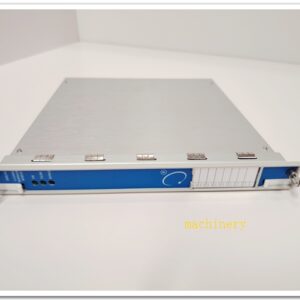
The ICSF08D1 is a modular high‑speed counter unit belonging to the legacy ABB Procontic CS31 PLC remote I/O system. It is widely deployed for pulse capture, encoder reading, frequency measurement and event counting on conveyors, flow meters, rotary machinery and packaging lines. This module features 8 optically isolated digital input channels, supporting high‑frequency pulse acquisition and counter functions. It communicates via the CS31 fieldbus back to the Procontic master controller, enabling distributed signal collection in factory automation, water treatment, material handling and machinery control. The CS31 system is phased out by ABB, so ICSF08D1 is mainly supplied as spare replacement for existing installed bases. It includes LED channel diagnostics, short‑circuit protection and DIN rail housing for cabinet installation.
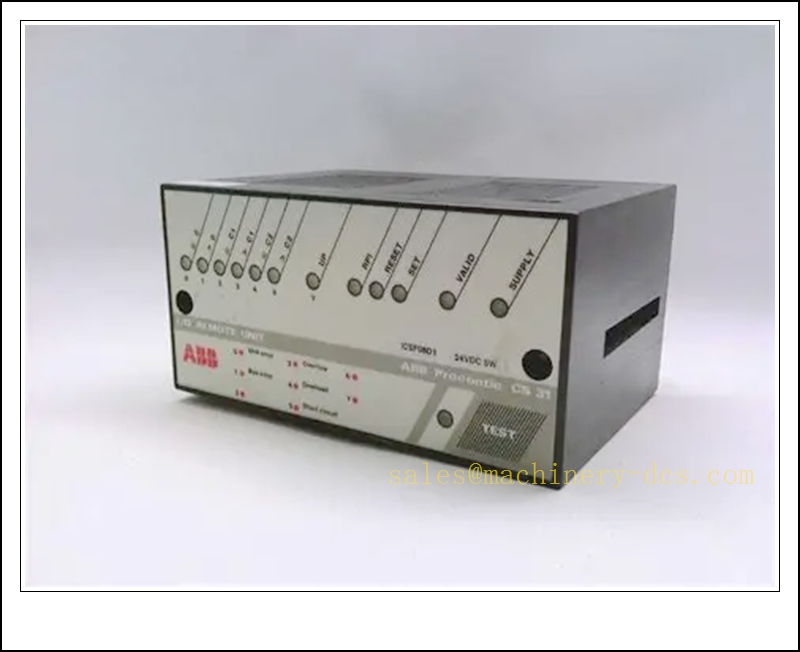
ICSF08D1
Main Technical Specifications
| Item | Parameter |
|---|---|
| Model | ICSF08D1 |
| Alternative Order No. | FPR3323101R1012 |
| Series | Procontic CS31 Remote I/O |
| Channel Configuration | 8 × optically isolated digital / counter inputs |
| Supply Voltage | 24 V DC (19.2 ~ 30 V DC) |
| Max Counting Frequency | Up to 1 MHz |
| Counter Range | 32‑bit counter |
| Fieldbus Interface | CS31 bus |
| Status Indication | LED per channel + module run/fault LED |
| Isolation | Optical isolation between field side and bus side |
| Mounting | Standard DIN rail |
| Operating Temperature | -20 °C ~ +60 °C |
| Storage Temperature | -40 °C ~ +85 °C |
| Humidity | 5% – 95% RH, non‑condensing |
| Protection Class | IP20 |
| Power Consumption | Approx. 3 W |
| Net Weight | ~0.35 kg |
| Product Status | Discontinued original production, spare stock only |
| Certifications | CE |
Quality Control Procedure
- Visual & Label Inspection: Verify ABB original marking, part number ICSF08D1 / FPR3323101R1012, serial number, PCB condition, no burn marks, corrosion or bent pins.
- Power Supply Test: Apply regulated 24 V DC power, confirm power LED lights up, no overheating or excess current.
- Channel Input Test: Inject 24 V DC signal to each of the 8 channels, check corresponding channel LED toggles correctly.
- High‑Speed Pulse Test: Feed pulse signal from signal generator to validate counter capture and frequency reading.
- Bus Communication Test: Pair with master interface board to verify bus registration and cyclic data exchange.
- Isolation & Short‑Circuit Protection Check: Test isolation resistance and verify fuse/protection response under short‑circuit condition.
- Diagnostic Function Check: Simulate open wire and fault conditions to confirm fault flag reporting.
- Parameter Retention Test: Download counter preset values, power cycle and confirm setpoints remain stored.
- Packaging & Traceability: Anti‑static packing, foam cushioning, serial‑number linked QC report before shipment.
Frequently Asked Questions (FAQ)
Q1: What system does ICSF08D1 belong to?A1: It is a remote I/O module for the ABB Procontic PLC system, cannot work standalone without a master.
Q2: What is the difference between and ICSF08E1?A2: is 24VDC sink/source counter input version; ICSF08E1 is the alternative variant with different input characteristic, not fully interchangeable.
Q3: Can be used with AC800M?A3: Not native. AC800M does not support bus directly. It is only for legacy Procontic controllers.
Q4: What signals can connect to this module?A4: NPN / PNP proximity sensors, incremental encoders, pulse flow transmitters, dry contact signals and other 24 V DC pulse sources.
Q5: Is still supported by ABB?A5: The Procontic platform is end‑of‑life. No new official production; available stock is for spare replacement only.
Q6: Does it support Modbus?A6: Native bus is . It does not have built‑in Modbus RTU; Modbus conversion requires external gateway hardware.
Installation & Configuration Guide
- Pre‑installation Preparation: Prepare 24 V DC regulated power supply, bus cable, terminal wiring, ESD wristband and Procontic programming software.
- DIN Rail Mounting: Clip module onto standard 35 mm DIN rail inside control cabinet. Keep minimum clearance for ventilation.
- Bus Wiring: Connect bus line, follow bus topology and install bus terminator at the two physical ends of the trunk. Missing terminator causes unstable communication.
- Field Wiring: Wire sensors, encoders or pulse signals to input terminals. Separate high‑power cables from signal wiring. Observe polarity for PNP/NPN devices.
- Power Connection: Connect 24 V DC supply to module power terminals and protective earth.
- Address Setting: Set the station address via DIP switch on the module; each remote unit must have unique address on the bus.
- Power‑on & Bus Scan: Switch on power, run bus scan from master controller, confirm the station is detected without bus fault.
- Channel Parameter Configuration: In Procontic software, define each channel as digital input, counter or frequency channel, set preset value, gate time and alarm thresholds.
- Commissioning Test: Trigger sensors and encoder pulses, verify counter value updates correctly on master side; check fault reporting for broken wire or short circuit.
- Project Backup: Save the complete hardware configuration and user program for site restore.
Warning: Do not hot‑plug bus or field sensor wires while powered. Verify terminal polarity before energising.
Related ABB Procontic Models & Order Number Recommendation (15 pcs)
| Model | Order Number | Description |
|---|---|---|
| ICSF08E1 | FPR3323101R1013 | CS31 8CH Digital Input Module, variant of ICSF08D1 |
| ICSF16D1 | FPR3323102R1011 | CS31 16DI Digital Input Module |
| ICSF16E1 | FPR3323102R1012 | CS31 16DI Alternative Input Module |
| ICSO08D1 | FPR3323201R1011 | CS31 8DO Digital Output Module |
| ICSO08E1 | FPR3323201R1012 | CS31 8DO Output Variant |
| ICSAO04D1 | FPR3323301R1011 | CS31 4CH Analog Output Module |
| ICSAI04D1 | FPR3323401R1011 | CS31 4CH Analog Input Module |
| ICSAI08D1 | FPR3323402R1011 | CS31 8CH Analog Input Module |
| ICST01D1 | FPR3323501R1011 | CS31 Terminal Base Unit |
| ICSM01D1 | FPR3323001R1011 | CS31 Master Interface Module |
| ICSM02D1 | FPR3323002R1011 | CS31 Redundant Master Module |
| CS31 Bus Cable | FPR3323901R1001 | CS31 Shielded Bus Cable |
| CS31 Terminator | FPR3323902R1001 | CS31 Bus Termination Resistor |
| ICSR01D1 | FPR3323601R1011 | CS31 Relay Output Module |
| ICSF04D1 | FPR3323103R1011 | CS31 4CH High Speed Counter Module |

 Send an Email