
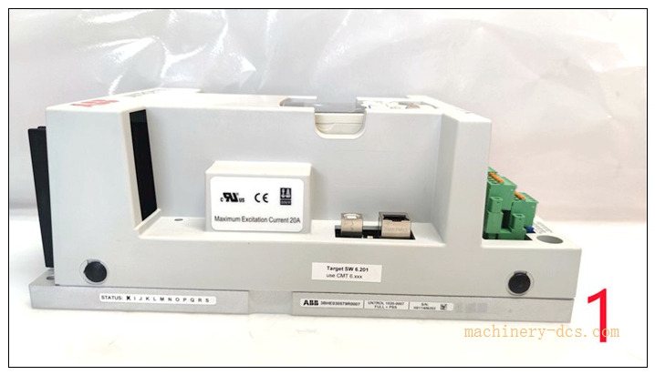
Description
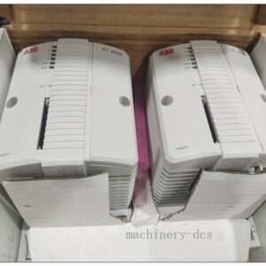
ABB 3BHE030579R0003 UNITROL 1020‑0003 BASIC Digital Excitation Controller / Automatic Voltage Regulator (AVR) for Synchronous GeneratorsABB Group
Product Core Overview
The 3BHE030579R0003 is the BASIC‑grade digital AVR excitation controller of ABB UNITROL 1020 series, designed for static excitation systems of small‑to‑medium‑capacity synchronous generators (100 kVA ~ 5 MVA). It executes digital PID voltage regulation, reactive power control, power‑factor control and generator‑parallel‑operation functions by processing PT/CT voltage‑current feedback signals, and adjusts generator excitation output to stabilize terminal voltage under load variation and grid disturbance.
Equipped with local LCD‑keyboard HMI, multi‑channel analog/digital I/O, RS‑485 communication interface and comprehensive generator‑oriented protection logics. The unit supports commissioning via CMT1000 PC tool, non‑volatile fault event logging, and seamless replacement for legacy UNITROL 1000‑15 BASIC controllers for retrofit projects. It is widely deployed for hydro‑units, diesel gen‑sets, industrial auxiliary generators and co‑generation power plants.
Notes:
- Order code: 3BHE030579R0003, commercial designation: UNITROL 1020‑0003 BASICABB Group.
- Country of origin: Switzerland / Spain / ChinaABB Group.
- Cabinet‑mount IP20 design, for indoor installation only.
- Supports multiple operating modes: AVR, VAR control, Power‑Factor control, manual field‑current control.
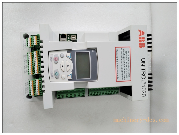
UNITROL 1020 3BHE030579R0003
Main Technical Specifications
| Item | Technical Parameter |
|---|---|
| Part Number | 3BHE030579R0003 (UNITROL 1020‑0003 BASIC)ABB Group |
| Manufacturer | ABB |
| Device Type | Digital Automatic Voltage Regulator / Excitation Controller |
| Applicable Generator Range | 100 kVA ~ 5 MVA synchronous generator |
| Regulation Accuracy | ±0.5 % typical (steady‑state) |
| AVR Response Time | ≤ 100 ms (3‑phase measurement) |
| Control Modes | AVR, Reactive Power, Power Factor, Manual Field‑Current |
| Power Supply | 12.5 VDC ~ 48 VDC wide‑range DC supply |
| Max Excitation Output Current | 40 ADC (continuous) |
| I/O Channels | 4 analog inputs, 6 digital inputs, 4 relay outputs; PT/CT measurement inputs |
| Communication | RS‑485, Modbus‑RTU protocol |
| Built‑in HMI | Local LCD + keypad for parameter setting & fault viewing |
| Protection Functions | Over‑excitation, under‑excitation, overvoltage, undervoltage, overcurrent, loss‑of‑field, field‑short‑circuit protection |
| Operating Temperature | −25 °C ~ +70 °C |
| Storage Temperature | −40 °C ~ +85 °C |
| Relative Humidity | 5 %‑95 % non‑condensing |
| Mounting | Cabinet screw‑on / panel mounting |
| Ingress Protection | IP20 (internal cabinet use) |
| Weight | 3.736 kgABB Group |
| Certifications | CE, UL, IEC 60146, IEEE 421.5 compliance |
Related Series & Model Recommendations (8+ Models)
- 3BHE030579R0003 UNITROL 1020‑0003 BASIC: Base basic excitation controller, RS‑485 only, no Ethernet.
- 3BHE030579R0004 UNITROL 1020‑0004 ADVANCED: Advanced version with Ethernet communication & IEC 61850 support.
- 3BHE030579R0001 UNITROL 1020‑0001: Compact entry‑level AVR for small diesel generator applications.
- UNITROL 1010: Cost‑optimized compact excitation controller for simple gen‑set projects.
- UNITROL 1030: High‑performance redundant‑ready excitation controller for medium‑large generators.
- UNITROL 1000‑15 BASIC: Legacy predecessor model, common retrofit target for 3BHE030579R0003 replacement.
- CMT‑1000 Software Tool: PC commissioning & parameterisation tool for UNITROL‑1020 series controllers.
- 3BHE024880R0001 UNITROL HMI‑02: Remote external HMI panel for door‑mount operation.
- 3BHE034578R0000 Excitation Power Unit: Matching power stage for UNITROL‑1020 control board.
- 3BHE031245R0000 Redundancy Interface Unit: For dual‑controller hot‑standby redundant excitation system configuration.
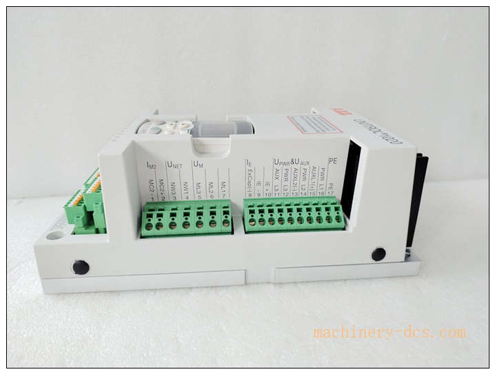
UNITROL 1020 3BHE030579R0003
Professional Quality Control & Factory Test Procedures
- Visual & Mechanical Incoming Inspection: Inspect housing, terminal blocks, front‑panel HMI display, label marking and screw terminals; record serial‑number for full‑lifecycle traceability.
- Full‑range Power Supply Test: Verify stable operation across the full DC supply range (12.5 VDC‑48 VDC), simulate voltage drop and surge disturbance.
- Measurement‑Input Calibration Test: Inject simulated PT voltage and CT current signals, calibrate voltage‑regulation closed‑loop accuracy to meet ±0.5 % specification.
- Protection‑Logic Function Test: Simulate over‑excitation, loss‑of‑field, overvoltage and over‑current fault conditions, verify alarm triggering and relay‑output action sequence.
- I/O Channel‑by‑channel Test: Validate all analog inputs, digital inputs and relay output channels for correct signal acquisition and switching performance.
- Communication Interface Test: RS‑485 Modbus‑RTU communication test, verify register read‑write and remote parameter access function.
- HMI & Event‑log Verification: Test local parameter modification, fault‑event recording, historical fault query and non‑volatile memory data retention after power‑off.
- Closed‑loop Regulation Dynamic Test: Simulate generator load step‑change, validate AVR dynamic response time and voltage‑stabilizing performance.
- Environmental Stress Screening: Temperature‑cycle test over full operating‑temperature range, damp‑heat aging test.
- EMC Electromagnetic Compatibility Test: ESD, surge, EFT‑burst test complying with IEC industrial standards.
- Final Full‑function Validation & Archiving: Complete system‑level acceptance test; bind all test‑reports with unit serial‑number before factory release.
New Module Installation & Commissioning Guide
6.1 Pre‑installation Preparation
Inspect unit for transit damage, confirm part‑number and serial‑number match purchase documents. Review generator nameplate parameters, excitation‑system drawings, PT/CT ratios and protection setting values. Prepare CMT1000 commissioning software, communication cable, anti‑static wrist‑strap. Perform generator lock‑out‑tag‑out safety procedures before installation work.
6.2 Mechanical Installation
Mount the UNITROL 1020 controller inside protection‑grade IP20 cabinet via screw mounting. Maintain adequate surrounding ventilation clearance for natural cooling; avoid installation adjacent to high‑heat power components. Install remote HMI panel if required.
6.3 Electrical Wiring
Connect DC control power supply within 12.5‑48 VDC rated range. Wire PT voltage‑measurement inputs and CT current‑measurement inputs strictly follow single‑line diagram. Wire analog/digital I/O signals for generator‑breaker interlock, alarm signal output. Connect RS‑485 Modbus bus to DCS/SCADA system. Complete reliable protective cabinet grounding. Separate signal cables from high‑power excitation cables to reduce EMI interference.
6.4 System Commissioning
- Power‑on the unit, check front‑panel power‑OK indicator and HMI boot‑up status.
- Input generator parameters, PT/CT ratios, AVR PID gains and protection threshold values via local HMI or CMT1000 PC tool.
- Perform open‑loop excitation test to verify excitation output polarity and current range.
- Switch to closed‑loop AVR mode, perform generator no‑load voltage‑regulation test, calibrate steady‑state voltage precision.
- Execute load‑step test, verify dynamic voltage‑response performance.
- Trigger each protection‑function simulation test, confirm alarm‑relay action and fault‑event log recording.
- Complete Modbus‑RTU communication debugging, verify remote status‑reading and alarm upload to upper‑level system.
- Save full parameter backup file. Put excitation controller into formal generator operation.
Application Scenarios & Product Features
7.1 Application Scenarios
3BHE030579R0003 (UNITROL1020‑0003 BASIC) applies to small‑medium synchronous generator static excitation systems: hydro‑power units, diesel‑engine generator sets, industrial co‑generation plants, factory auxiliary power generators, offshore auxiliary generation equipment, and legacy excitation‑system retrofit projects.
7.2 Core Product Features
- Multi‑mode Excitation Regulation: Supports AVR voltage regulation, VAR / power‑factor control, manual field‑current control for generator parallel‑operation.
- Multiple Built‑in Generator Protections: Comprehensive excitation‑related protection logics to safeguard generator rotor and excitation power‑unit.
- Local HMI & PC Tool Support: On‑site parameter adjustment and fault diagnosis either via front‑panel keypad‑LCD or CMT1000 PC commissioning software.
- Modbus‑RTU Communication: Real‑time data uploading, remote monitoring and alarm transmission to plant DCS/SCADA.
- Non‑volatile Event‑log: Stores fault records after power loss for post‑fault analysis.
- Wide‑range DC power supply: Adapt to various plant‑site DC control‑power sources.
- Retrofit‑friendly: Drop‑in replacement for old UNITROL 1000‑15 BASIC excitation controllers.
- Industrial‑grade EMC & environmental performance: Designed for harsh power‑plant cabinet environments.
Frequently Asked Questions (FAQ)
Q1: What is the difference between 3BHE030579R0003 (BASIC) and UNITROL1020‑0004 (ADVANCED)? A: The BASIC version (3BHE030579R0003) is equipped with RS‑485 Modbus‑RTU only. The ADVANCED model adds Ethernet port and supports IEC 61850 protocol for modern substation communication requirements.
Q2: Can this unit be used for generator parallel‑operation on grid? A: Yes. It supports VAR and power‑factor control modes for grid‑parallel synchronous generators. Proper tuning of PID parameters and interlock‑logic configuration is required.
Q3: Why does AVR produce over‑voltage oscillation during generator no‑load test? A: Common causes: inappropriate PID gain setting, wrong PT‑wiring polarity, incorrect PT‑ratio parameter entry, or interference on measurement signal cables. Re‑tune PID parameters and check PT wiring.
Q4: Is hot‑swap replacement supported for this controller? A: No. For single‑controller excitation system, power‑down is required before replacement. For dual‑redundant excitation system, switch over to standby channel before removing the faulty unit.
Q5: Can I replace UNITROL 1000‑15 BASIC directly with 3BHE030579R0003? A: Mechanical form‑fit is mostly compatible. Need to re‑check wiring definition, upload new project parameters, and perform full closed‑loop commissioning; direct plug‑and‑play without commissioning is not allowed.
Q6: What software is used for PC‑based commissioning? A: CMT 1000 is the dedicated configuration and monitoring tool for UNITROL 1020 series controllers.
Q7: Is on‑site disassembly and repair allowed? A: No. This is factory‑calibrated integrated excitation control equipment. Unauthorized disassembly voids warranty and safety compliance. Defective units should be returned to ABB authorized service centre.

 Start Chat


 Send an Email


