
Description
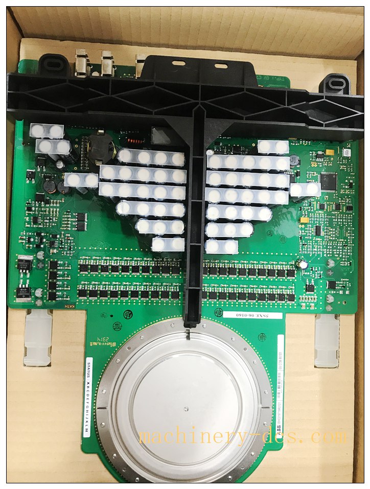
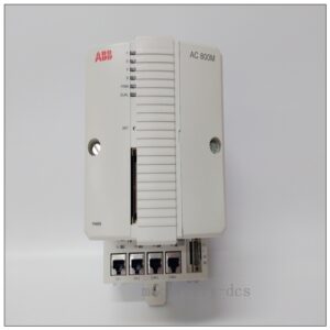
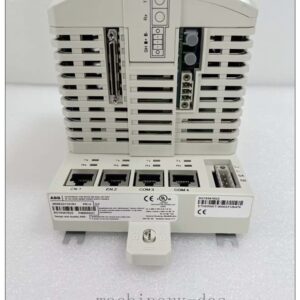
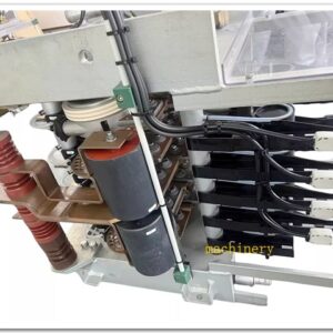
ABB 3BHB021400R0002 Integrated IGCT Assembly (Core semiconductor:5SHY4045L0004)
Product Detailed Description
3BHB021400R0002 is a complete assembled IGCT (Integrated Gate‑Commutated Thyristor) power stack unit for ABB medium‑voltage drive systems. This assembly integrates the 5SHY4045L0004 high‑power IGCT chip, gate‑driver circuit board, snubber components, power terminals and mechanical pressure‑contact hardware. It serves as core high‑voltage power switching component inside ABB ACS6000 medium‑voltage converters, performing high‑speed power switching for medium‑voltage motor drive, active front‑end rectifier and inverter arms. Gate‑driver board receives optical trigger commands from drive control unit, delivers precise gate‑commutated turn‑on / turn‑off pulse for IGCT semiconductor. Original manufacturing is discontinued; new‑old‑stock, factory‑tested refurbished and field‑pulled spare assemblies circulate for medium‑voltage drive maintenance and plant life‑extension projects.
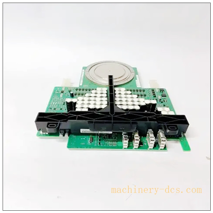
5SHY4045L0004 3BHB021400R0002
Technical Parameters
| Item | Specification |
|---|---|
| Manufacturer | ABB |
| ABB Assembly P/N | 3BHB021400R0002 |
| Internal IGCT chip | 5SHY4045L0004 |
| Product Status | OEM Discontinued, spare‑part‑only supply |
| Device Type | Integrated Gate‑Commutated Thyristor complete stack assembly |
| Repetitive peak off‑state voltage VDRM | 4500 V |
| RMS on‑state current IT(RMS) | 1200 A |
| Max junction temperature Tj | 140 ℃ |
| Trigger interface | Optical fiber trigger signal for gate‑driver board |
| Cooling requirement | Liquid water‑cooled cold‑plate mounting; strict thermal contact required |
| Gate‑driver power | Auxiliary low‑voltage power supply for internal gate‑driver PCB |
| Mechanical form | Press‑pack IGCT integrated assembly with gate‑driver PCB |
| Operating base plate temp(Tc) | ‑20 ℃ ~ +85 ℃ |
| Storage Temperature | ‑40 ℃ ~ +125 ℃ |
| Humidity | 5‑85 % RH non‑condensing |
| Weight | ≈9.8 kg |
| Dimension | 345 × 245 × 195 mm |
| Certifications | CE, IEC 60747‑6, SEMI‑S2 for power conversion equipment |
| Typical host system | ABB ACS6000 medium‑voltage variable‑frequency drive platform |
Compatibility & Installation Traps
Compatibility
- ABB ACS6000 medium‑voltage converter power‑cell cabinets, rectifier & inverter power arms
- Matching optical trigger fiber cables, gate‑driver auxiliary power supply unit
- Specified water‑cooled cold‑plate heat sink assembly for ACS6000 cabinet
- ACS6000 control unit executing IGCT firing sequence and drive protection logic
Critical note: This is a complete press‑pack IGCT assembly including gate‑driver PCB. Cannot separate and reuse only bare 5SHY4045L0004 chip without matching original gate‑driver hardware. Drive firmware and power‑cell configuration parameters must match; different hardware revisions are not drop‑in compatible without cell‑level commissioning.
Installation Pitfalls
- Press‑pack clamping torque critical risk: Press‑pack IGCT relies on precise mechanical compression force. Incorrect bolt torque will cause excessive thermal resistance, local overheating, early device burnout or internal contact arcing. Must strictly follow ABB specified torque value.
- Cold‑plate cooling‑surface damage: Water‑cooled contact surface must stay flat, scratch‑free and clean. Scratches, dirt or foreign particles between assembly base and cold‑plate degrade heat dissipation and trigger junction over‑temperature failure.
- High‑voltage safety warning: Always implement full lock‑out‑tag‑out, complete DC‑bus capacitor discharge before service. Residual high‑voltage charge remains in snubber capacitors long after power‑off.
- Optical fiber handling constraints: Trigger optical fibers cannot be bent below minimum bend radius; fiber scratch, fracture or mis‑alignment will lead to loss‑of‑gate‑pulse, IGCT mis‑fire or cell short‑circuit fault.
- Gate‑driver auxiliary power requirement: After replacement, verify gate‑driver auxiliary low‑voltage power is within specified tolerance; under‑voltage causes unreliable IGCT turn‑off and catastrophic power‑cell damage.
- ESD extreme sensitivity: Gate‑driver PCB and IGCT gate‑trigger terminals are static‑sensitive. ESD wrist‑strap and anti‑static mat are mandatory for all handling operations; invisible ESD damage induces random mis‑firing without visible burn marks.
- Part‑number full marking verification: Confirm complete assembly marking 3BHB021400R0002. Bare chip 5SHY4045L0004 alone cannot substitute this complete assembled unit.
- Post‑replacement cell test mandatory: Spare refurbished assembly requires power‑cell level low‑voltage & high‑voltage commissioning test after installation; cannot directly run full‑load production without verification.
Standard Operating Procedure (SOP)
- Pre‑work: Execute plant lock‑out‑tag‑out for medium‑voltage drive unit. Isolate medium‑voltage incoming power, confirm DC‑bus full discharge, implement high‑voltage safety permit procedure. Wear certified ESD anti‑static wrist strap and insulating safety tools.
- Data backup: Backup ACS6000 drive parameters, power‑cell configuration, fault log, record original assembly hardware revision number.
- Module removal: Confirm zero residual voltage inside power‑cell cabinet. Disconnect optical trigger fibers, auxiliary gate‑driver power connectors, main high‑power bus‑bar terminals. Release clamping bolts following specified torque‑release sequence, extract 3BHB021400R0002 IGCT assembly. Inspect cold‑plate cooling surface, bus‑bar contacts, fiber‑connector interfaces for scratch, oxidation or contamination.
- Incoming inspection: Visual inspect spare assembly for mechanical damage, gate‑driver PCB trace damage, connector integrity. Verify full assembly part‑number marking and hardware revision. Inspect press‑pack contact surfaces for scratches or foreign debris.
- Mechanical mounting: Carefully position new IGCT assembly onto cleaned cold‑plate surface. Apply clamping bolts following ABB defined tightening sequence and precise torque setting. Avoid offset or skewed placement. Re‑install high‑power bus‑bar connections to specified torque.
- Cabling & fiber installation: Re‑connect gate‑driver auxiliary power cables, install optical trigger fibers respecting minimum bend radius; ensure fiber connectors are clean and fully seated.
- Power‑on commissioning: Restore auxiliary cabinet control power and gate‑driver supply. Perform low‑voltage power‑cell diagnostic test. Verify optical trigger signal integrity and gate‑driver status. If hardware revision differs, check drive parameter compatibility. Execute capacitor charging pre‑charge sequence before full medium‑voltage energization.
- Functional validation: Run drive cell‑level diagnostic routines. Execute no‑load drive test, check gate‑driver status, cell voltage balance, temperature monitoring values. Gradually apply load, monitor IGCT junction temperature and power‑cell fault counters. Confirm no mis‑fire, over‑temperature or snubber‑related alarms persist.
- Documentation: Fill drive maintenance log, archive assembly serial‑number, torque‑record and commissioning test report. Properly package defective removed IGCT assembly. Release lock‑out‑tag‑out permit only after full acceptance‑test successfully completed.
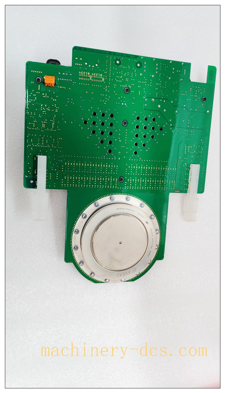
5SHY4045L0004 3BHB021400R0002
Application Scenarios
‑ Medium‑voltage drive for large‑power industrial motor: fans, pumps, compressors in power‑plant, mining, metallurgy ‑ Medium‑voltage converter active‑front‑end rectifier and inverter power‑cell arms ‑ Heavy‑industry large‑motor variable‑speed control ‑ Legacy ABB medium‑voltage drive preventive maintenance & life‑extension retrofit projects
Matching & Supporting Components
- power‑cell cabinet and water‑cooled cold‑plate heat‑sink assembly
- Optical trigger fiber cables for IGCT gate‑driver unit
- Gate‑driver auxiliary regulated low‑voltage power‑supply
- High‑current bus‑bar connection hardware, specified‑torque bolt sets
- ABB drive control unit and commissioning service tool
- ESD‑shielded anti‑static storage container for IGCT assembly storage
Brand‑Related Alternative & Recommended Models
- 3BHB021400R0001: Previous hardware revision of same IGCT assembly; verify gate‑driver firmware compatibility before substitution
- 5SHY4045L0004: Bare IGCT semiconductor chip only; cannot be directly used, needs full gate‑driver and mechanical press‑pack assembly
- ABB IGCT‑based medium‑voltage converter new‑generation power‑cell units: For complete system‑migration projects

 Start Chat


 Send an Email


