
Description
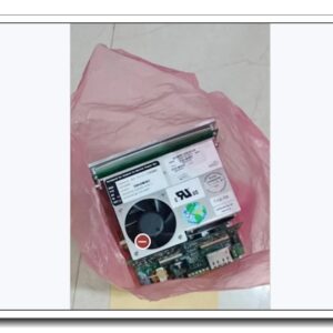
ABB 3BDH000741R1, AI930S – S900 Series 8-Channel Analog Input Module
Core Product Introduction
The 3BDH000741R1 (AI930S) is an analog input module for the ABB S900 distributed I/O system, commonly paired with AC800M controllers in process automation. It acquires analog field signals from transmitters, sensors and transducers and converts them into digital values for the DCS controller. This module supports standard 4–20 mA and 0–20 mA current signals with intrinsic galvanic isolation per channel. It features built-in diagnostics for wire break, short circuit and module fault, with front-panel LED status indication. S900 I/O communicates to the controller via ModuleBus, delivering high reliability for continuous process control in chemical, power, pulp & paper, water treatment and oil & gas applications. It is widely stocked as a spare part for existing installed S900 racks.
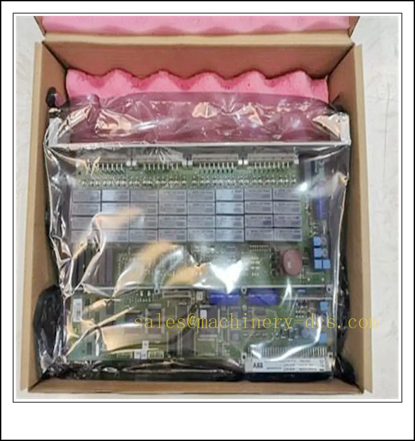
CTI121-P EX 3BDH000741R1
Main Technical Specifications
| Item | Parameter |
|---|---|
| Part Number | 3BDH000741R1 |
| Type | AI930S Analog Input Module |
| I/O Series | ABB S900 Remote I/O |
| Channel Count | 8 isolated analog input channels |
| Signal Type | 4–20 mA / 0–20 mA |
| Resolution | 16-bit |
| Channel Isolation | Galvanic isolation between each channel and bus side |
| Diagnostics | Wire break detection, short-circuit detection, module fault |
| Fieldbus Interface | ModuleBus for AC800M |
| Status Indication | Module RUN/FAULT LED + per-channel diagnostic LEDs |
| Supply Voltage | 24 V DC (19.2 ~ 30 V DC) |
| Power Consumption | Max 2.8 W |
| Operating Temperature | 0 °C ~ +60 °C |
| Storage Temperature | -40 °C ~ +85 °C |
| Humidity | 5%–95% RH, non-condensing |
| Protection Class | IP20 |
| Mounting | S900 backplane base unit |
| Weight | Approx. 0.32 kg |
| Certifications | CE, cULus, ATEX / IECEx Zone 2 approved |
| Lifecycle Status | EOL, spare stock only |
Quality Control Procedure
- Visual & Label Inspection: Check original ABB marking, part number 3BDH000741R1, serial number, PCB, terminal connectors and front housing; verify no burn marks, corrosion or bent pins.
- Power Cycle Test: Apply regulated 24 VDC supply, confirm RUN LED lights up, no overheating or abnormal current draw.
- Channel Signal Calibration Test: Inject precision 4–20 mA signal to every channel, verify reading accuracy at 4 mA, 12 mA and 20 mA.
- Diagnostic Function Test: Simulate open wire and short-circuit conditions on each channel to confirm fault detection and FAULT LED trigger.
- ModuleBus Communication Test: Install on baseplate, connect ModuleBus and verify handshake and cyclic data exchange with AC800M CPU.
- Isolation Resistance Test: Verify isolation performance between field side and bus backplane side.
- LED Indicator Verification: Confirm RUN, FAULT and individual channel diagnostic LEDs respond correctly to status changes.
- Configuration Retention Test: Download hardware configuration, power cycle and confirm settings are retained.
- Compatibility Check: Confirm hardware revision compatibility with target AC800M firmware.
- Packaging & Traceability: Anti-static sealing, foam cushioning, serial-number traceable QC report before shipment.
Frequently Asked Questions (FAQ)
Q1: What controller family works with 3BDH000741R1 AI930S?A1: It belongs to I/O system and works with ABB AC800M controllers via ModuleBus. It cannot run standalone.
Q2: What is the difference between AI930S (3BDH000741R1) and AI930?A2: AI930S is the isolated variant with enhanced channel isolation and hazardous area certification; standard AI930 has different isolation specs and is not fully interchangeable.
Q3: Can this module read RTD or thermocouple signals?A3: No. only supports 0–20 mA / 4–20 mA current transmitters. Use dedicated RTD/TC modules for temperature sensors.
Q4: Does support hot swap?A4: Yes, modules support hot swapping when the system is configured properly, but follow ABB procedure to avoid bus disturbance.
Q5: Is still in production?A5: The I/O series is end-of-life. New production is discontinued; available units are spare stock for legacy plant maintenance.
Q6: What baseplate is required for ?A6: It must be mounted onto a matching base terminal unit for wiring and ModuleBus connection.
Installation & Configuration Guide
- Pre-install Preparation: Prepare 24 VDC power supply, base unit, shielded twisted-pair field cables, ModuleBus cable, ESD wristband and Control Builder M software.
- Baseplate Mounting: Install the base unit onto standard DIN rail inside the control cabinet.
- Field Sensor Wiring: Wire 4–20 mA transmitters to module terminals, use shielded cable and single-point grounding for each signal loop.
- Module Insertion: Align and clip the module into the base unit, lock the latch.
- ModuleBus Connection: Connect ModuleBus to the base, install bus terminators at both ends of the ModuleBus trunk.
- Power Wiring: Apply 24 VDC power to the rack and protective earth.
- Power-up & Bus Scan: Energize the rack, run hardware scan from AC800M in Control Builder M, confirm the module is detected without bus fault.
- Channel Parameter Setup: Assign each channel signal range (4–20 mA), enable wire-break detection and define scaling for engineering units.
- Loop Commissioning: Apply signal from field transmitters, check raw and scaled values on controller tags, validate fault alarm response.
- Project Backup: Save the complete hardware configuration and application project file for future restore.
Warning: Do not mix 24 VDC digital signals and analog signal loops in the same cable tray without shielding. Verify loop polarity before energizing transmitters.
Related ABB Models & Order Number Recommendation (15 pcs)
| Model | Order Number | Description |
|---|---|---|
| AI930 | 3BDH000740R1 | 8CH Analog Input Module, non-S version |
| AO930S | 3BDH000742R1 | 8CH Analog Output Isolated Module |
| DI930S | 3BDH000743R1 | 16CH Digital Input Isolated Module |
| DO930S | 3BDH000744R1 | 16CH Digital Output Isolated Module |
| AI950S | 3BDH000745R1 | RTD Temperature Input Module |
| AI960S | 3BDH000746R1 | Thermocouple Input Module |
| CI930F | 3BDH000747R1 | Fieldbus Communication Interface |
| Base Unit | 3BDH000748R1 | Standard Terminal Base |
| TB930 | 3BDH000749R1 | Terminal Block Accessory |
| ModuleBus Terminator | 3BDH000750R1 | ModuleBus End Terminator |
| TU930S | 3BDH000751R1 | Isolated Terminal Unit |
| DI950 | 3BDH000752R1 | 32CH Digital Input Module |
| DO950 | 3BDH000753R1 | 32CH Digital Output Module |
| Power Module | 3BDH000754R1 | Rack 24VDC Power Supply |
| TK931 | 3BDH000755R1 | ModuleBus Shielded Cable |

 Send an Email