
Description
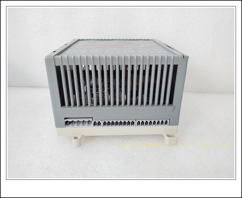
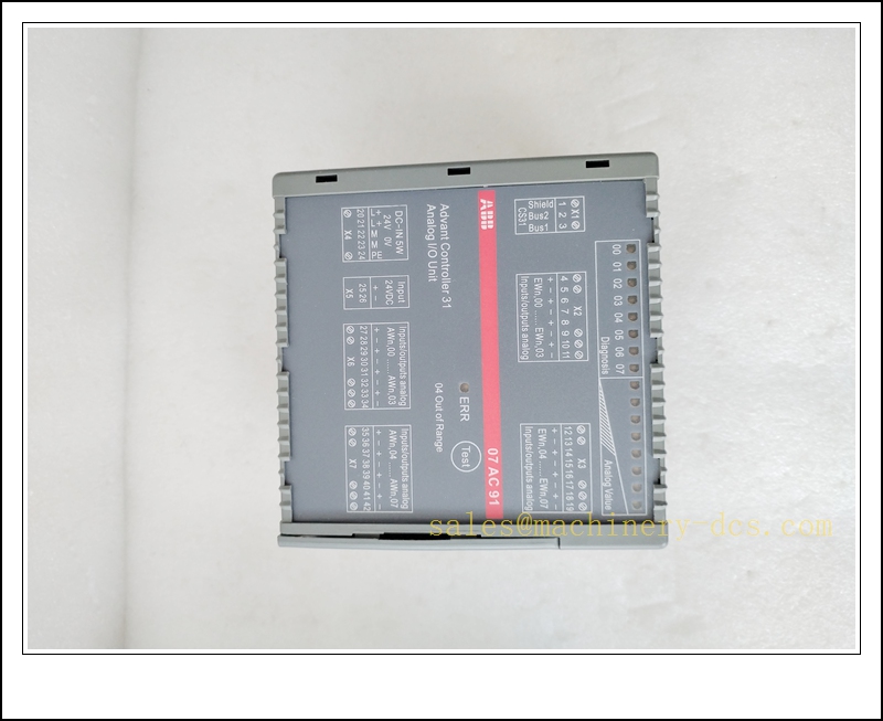
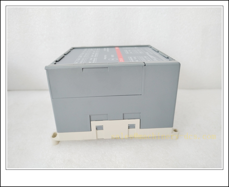
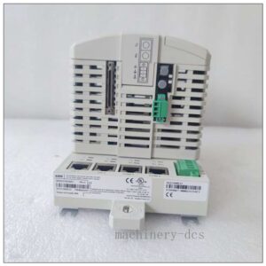
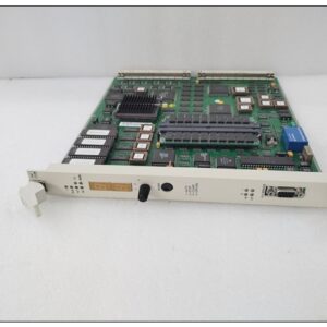
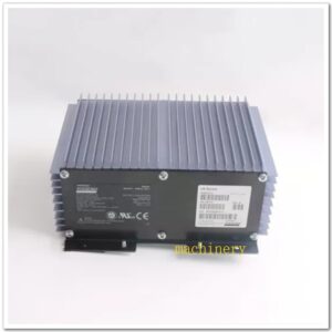
ABB 07AC91 Configurable Analog I/O Slave Module for AC31 / CS31 Fieldbus
Product Description
The 07AC91, with alternate part number GJR5252300R0101, is a compact distributed analog I/O slave unit designed for ABB Advant Controller 31 (AC31) automation systems over the CS31 RS485 fieldbus. It supports two hardware operating modes selected via on-board DIP switches. In 12-bit mode, it provides 8 configurable analog input channels plus 8 analog output channels; in 8-bit mode, all 16 channels are configurable in pairs as either input or output. It accepts standard industrial voltage and current signals for transmitters, sensors and modulating valves, performs A/D and D/A conversion locally, and exchanges cyclic process data with the AC31 master controller on the CS31 bus. Equipped with pluggable screw terminals and built-in channel diagnostics, this module is widely used as remote analog I/O for legacy ABB process control systems and is factory-discontinued, mainly supplied as maintenance spare parts.
Technical Specifications
- Brand: ABB
- Part Number: 07AC91, Alternative Code: GJR5252300R0101
- Series: AC31 Advant Controller 31
- Type: CS31 Fieldbus Analog I/O Slave Module
- Channel Modes:
- 12-bit mode: 8 AI + 8 AO
- 8-bit mode: 16 channels, paired AI/AO configurable
- Signal Ranges: ±10 V, 0–10 V, 0–20 mA, 4–20 mA
- Resolution: 12 bit or 8 bit (DIP switch selectable)
- Power Supply: 24 VDC, 18–30 VDC operating range
- Fieldbus: CS31, RS485 physical layer
- Termination: Pluggable screw terminal, wire size 0.08–1.5 mm²
- Diagnostics: Channel open circuit, short circuit, bus communication fault, module self-test
- Protection Class: IP20
- Mounting: DIN rail TH35
- Operating Temperature: -10 °C ~ +55 °C
- Storage Temperature: -20 °C ~ +70 °C
- Relative Humidity: 5% ~ 95 %, non-condensing
- Approximate Weight: 0.81 kg
- Certification: CE
07AC91F
Application Scenarios
- Petrochemical plant remote field analog signal collection and control
- Water and wastewater treatment flow, level, pH closed-loop regulation
- Power plant auxiliary boiler analog monitoring and valve positioning
- Cement and mining process variable remote I/O stations
- HVAC central plant chilled water valve and sensor control
- Pulp and paper mill pressure and temperature modulating control
- Retrofit and spare replacement for legacy ABB AC31 CS31 distributed I/O racks
- General industrial distributed analog control for 4-20mA transmitters
8 Related ABB Model Recommendations
- 07AI91 – AC31 Analog Input Module
- 07AO91 – Analog Output Module
- 07DI92 – Digital Input Module
- 07DO92 – Digital Output Module
- 07KT98 – CPU Master Controller
- DC501- – Bus Adapter
- 07AC91-AD – AC500 replacement adapter for 07AC91
- 07PS651 – Power Supply Module
Compatibility & Installation Pitfalls
Compatibility
- Developed for ABB Advant Controller 31 platform, communicates as slave; not native to AC500, 800xA without adapter.
- Operating mode and channel type must be set by DIP switches before commissioning; software-only configuration cannot override hardware mode.
- Requires bus master such as 07KT98; it cannot run standalone without an controller.
- Field signal wiring must match selected range (voltage or current); mixing signal types on one channel causes measurement failure.
- The module is discontinued by ABB; firmware is fixed, no new feature upgrades available.
- When replacing with 07AC91-AD adapter for AC500, program modification may be required.
Installation Pitfalls
- Isolate 24VDC supply and bus power before removing or inserting the module; live hot-swap is not supported.
- bus cable must be shielded twisted pair and fitted with proper bus termination resistor at the physical bus endpoints.
- Analog field cables must be separated from high-power VFD and motor cables to avoid noise and signal drift.
- Check DIP switch settings carefully after replacement; incorrect mode will lead to all I/O mapping mismatch.
- Current loop wiring must maintain correct polarity; reversed 4–20mA transmitters produce negative or invalid readings.
- Do not overload output channels; sustained short-circuit triggers channel fault and stops control output.
- Keep DIN rail cabinet ventilation unobstructed; high ambient temperature degrades conversion accuracy.
- After replacement, verify slave address matches the original configuration; duplicate bus addresses cause total bus failure.
07AC91F
Standard Operating Procedure (SOP)
SOP for 07AC91 Analog I/O Module Inspection, Installation and Functional Test
- Pre-Installation Inspection Examine the module housing, terminal connector and PCB for physical damage, burnt traces or contamination. Confirm part number 07AC91 / GJR5252300R0101. Verify compatibility with CPU, bus topology and field sensor/actuator signal types. Review I/O drawings and apply lockout-tagout to the 24 VDC supply and fieldbus.
- DIN Rail Installation Clip the module onto the TH35 DIN rail. Set DIP switches for 12-bit or 8-bit operating mode and confirm slave address. Wire the 24 VDC supply, bus cable, and analog field signals to the pluggable terminal block. Separate low-level analog wiring and bus cables from high-energy power circuits and implement EMC shielding grounding per ABB documentation.
- Controller Configuration Restore 24 VDC power. Connect to the programming tool, confirm the 07AC91 slave is recognized on the bus. Map each analog channel, configure signal range, scaling and fault handling. Download the validated application to the master and save an offline backup of the project. Resolve bus address, communication and module identification alarms before field testing.
- Channel and Diagnostic Test Inject calibrated reference signals (4mA,12mA,20mA or ±10V) to each analog input channel and verify scaled readings within tolerance. Force each analog output point and confirm actuator response. Simulate open wire and short-circuit faults to verify diagnostic alarm reporting. Record measurement accuracy and fault response in the test log.
- Process Commissioning Remove field signal isolation only after point-level testing passes. Enable closed-loop control and monitor signal stability under normal process conditions. Confirm channel faults trigger pre-defined safe output states and generate controller alarms without uncontrolled valve movement.
- Return to Service Reset fault latches and acknowledge diagnostic messages. Remove lockout-tagout. Monitor bus health, module status and analog signal quality through the supervised observation period. Notify operations that the 07AC91 analog I/O module is commissioned and ready for process control.
- Periodic Maintenance and Replacement During scheduled shutdown, inspect DIN rail mounting, terminal torque, cable shielding and DIP switch integrity. Perform analog loop proof-test according to plant maintenance schedule. If persistent bus or channel faults cannot be cleared, isolate power and bus before replacement. After fitting the spare module, recheck DIP switch address and mode, reload I/O mapping and complete full point and loop testing before returning online.

 Start Chat


 Send an Email


