
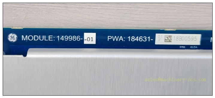
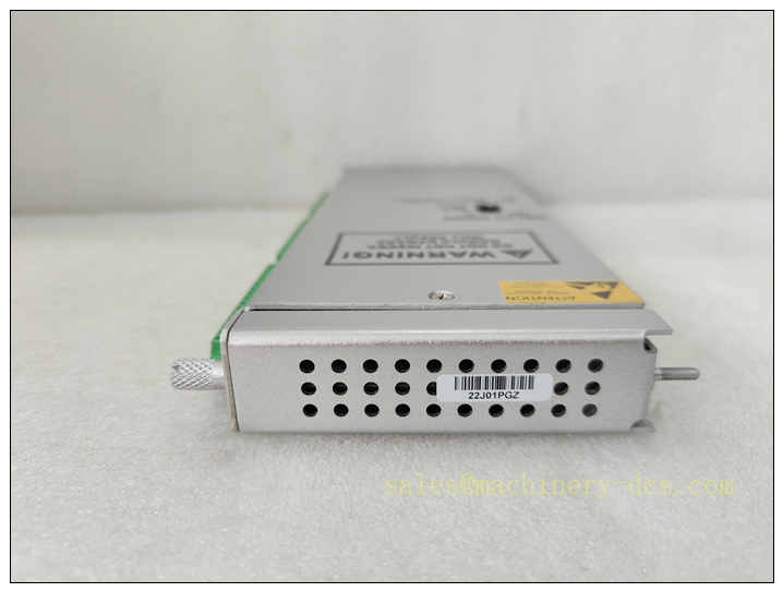
Description
3500/33 SIL2-01-00 Bently Nevada 16-Channel SIL2 Certified Relay Output Module for Machinery Protection System
Product Overview & Detailed Description
The 3500/33 SIL2-01-00 is a high-integrity, safety-certified 16-channel relay output module designed exclusively for the Bently Nevada 3500 machinery protection platform. As a core safety output component compliant with strict SIL2 functional safety standards, this module converts internal system monitoring data and alarm logic into hardwired dry-contact switching signals, enabling direct interlock control for industrial equipment, ESD (Emergency Shutdown) systems, and DCS remote signal transmission.
Featuring 16 independent configurable SPDT relay channels, the module supports flexible definition of alarm, warning, trip, and fault status outputs for vibration, temperature, speed, and displacement monitoring parameters. All relay circuits adopt epoxy-sealed industrial-grade design, with excellent anti-interference, dustproof and anti-aging performance, adapting to long-term stable operation in harsh industrial environments. The SIL2 certification validates its reliability for safety instrumented system (SIS) applications, providing deterministic fault response and low failure rate to meet industrial safety risk control requirements. The 01-00 configuration represents standard hardware layout and non-customized factory calibration, suitable for mainstream industrial safety protection and equipment interlock scenarios without special industry customized modifications.
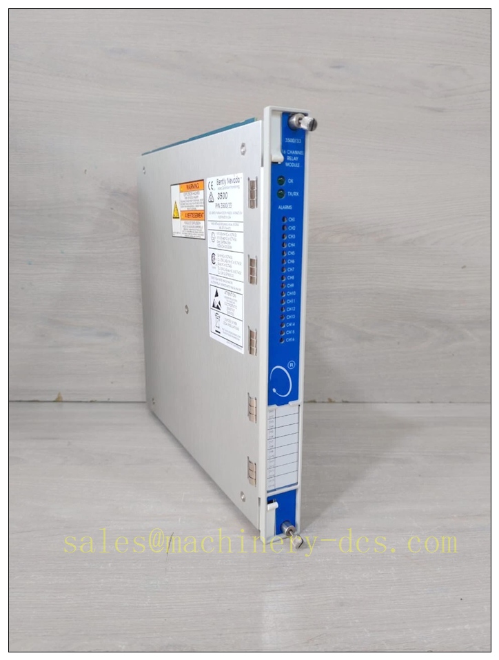
3500/33 SIL2-01-00
Core Technical Parameters
3.1 Relay Electrical Specifications
- Channel Quantity: 16 independent SPDT (Single Pole Double Throw) relay channels
- Resistive Load Rating: 5 A @ 250 VAC; 5 A @ 125 VDC
- Inductive Load Rating: 0.5 A @ 125 VDC
- Maximum Switching Power: 1200 VA (AC), 70 W (DC)
- Minimum Switching Load: 100 mA @ 5 VDC (ensures low-signal contact reliability)
- Contact Configuration: Isolated dry contact, no common power loop between channels
- Switching Response Time: ≤ 10 ms fast response for safety trip interlock
3.2 System & Safety Parameters
- Safety Integrity Level: Certified for functional safety system integration
- Power Consumption: Max 5.8 W under full-load operation
- Fault Diagnosis: Built-in self-diagnosis for relay circuit fault, open/short circuit detection
- Configuration Mode: Software programmable via 3500 Rack Configuration Software
3.3 Environmental & Physical Parameters
- Operating Temperature Range: -20 °C to +65 °C (-4 °F to +149 °F)
- Storage Temperature Range: -40 °C to +85 °C (-40 °F to +185 °F)
- Relative Humidity: 0%–95% non-condensing
- Construction: Epoxy-sealed relay unit, anti-vibration and anti-corrosion structure
- Form Factor: Standard 3500 series half-height module, hot-swappable design
- Compliance Standards: IEC 61508 (), API 670, CE EMC/LVD
Compatibility & Installation Pitfalls
4.1 System & Hardware Compatibility
This module is fully compatible with all standard Bently Nevada 3500 series 19-inch rack systems (3500/05 chassis) and supports hot-swap replacement without system shutdown. It matches all mainstream monitoring modules including 3500/40 proximity monitors, 3500/42 vibration monitors, 3500/50 temperature monitors, and 3500/25 keyphasor modules. It supports seamless signal linkage with DCS, PLC, and ESD safety systems via dry-contact output. It is compatible with 3500 series redundant power supplies and standard rack interface modules, and can be mixed-installed with SIL-certified monitoring modules for integrated safety system configuration.
4.2 Critical Installation Pitfalls & Common Errors
- Overload Switching Risk: Strictly prohibit exceeding rated inductive load parameters. Inductive equipment such as contactors and solenoid valves must be equipped with external freewheeling diodes or surge suppressors; overcurrent will cause relay contact ablation and invalidate safety certification.
- Channel Short-Circuit Damage: The 16 relay channels are independently isolated, but parallel connection of multiple channels for high-current output is forbidden. Parallel wiring will lead to internal circuit current imbalance and permanent module damage.
- Hot-Swap Operation Specification: Hot swapping is allowed for non-safety-related channels only. For safety trip channels, system lockout-tagout (LOTO) power-off operation is mandatory during replacement or wiring modification to avoid accidental equipment tripping.
- Wiring Anti-Interference Requirements: Relay output strong-current control wiring must be physically separated from sensor weak-signal wiring (minimum 50mm isolation). Mixed routing will cause signal interference, false alarms or missed trips.
- Temperature Derating Risk: When installed in fully sealed cabinets without ventilation, long-term operation above 55°C will reduce relay service life and safety integrity. For high-temperature sites, forced ventilation or derating use is required.
- SIL Configuration Validity Restriction: Arbitrary modification of factory default safety parameter settings in configuration software will cancel certification validity. Safety parameter adjustment must follow official safety manual specifications.
Standard Operating Procedure (SOP)
5.1 Pre-Installation Inspection
Verify module model integrity (3500/33 -01-00) and valid certification report; inspect module appearance, terminal pins and sealing structure for damage; confirm rack system version and configuration software compatibility; check on-site load parameters to ensure matching module rated capacity; prepare isolated wiring tools and anti-static equipment.
5.2 Standard Installation & Commissioning Steps
1. Implement LOTO safety procedure for safety loop wiring operation; 2. Insert the module into the designated slot of 3500 rack and fasten the locking handle to ensure reliable backplane contact; 3. Complete on-site load wiring in strict accordance with channel definition, separate strong and weak current cables, and fix wiring terminals firmly; 4. Power on the system, connect 3500 configuration software, read online module status, and configure channel alarm/trip logic parameters; 5. Perform single-channel simulation test to verify relay pull-in and release accuracy; 6. Conduct full-loop linkage test with ESD/DCS system to confirm safety interlock function; 7. Save configuration files and complete safety commissioning records.
5.3 Daily Operation & Maintenance
Real-time monitor module online status, channel fault alarm and relay action records through the system host; quarterly inspect wiring terminal tightness and cable aging status; semi-annually conduct channel function simulation test to eliminate contact failure risks; annually calibrate safety logic parameters and verify functional integrity; regularly clean module surface dust to ensure heat dissipation.
5.4 Fault Replacement Procedure
Cut off the safety loop external power and implement LOTO isolation; mark and remove all channel wiring; disassemble the faulty module and install a new certified module; restore wiring strictly according to the original channel correspondence; re-configure logic parameters and complete full-function test; confirm normal interlock action before resuming formal operation.
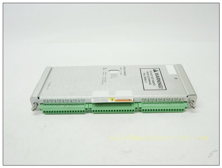
3500/33 SIL2-01-00
Application Scenarios
The 3500/33 -01-00 module is widely used in safety-critical industrial machinery protection and safety interlock scenarios requiring functional safety certification, including: petrochemical refining and chemical production turbine and compressor safety trip systems, oil and gas onshore and offshore platform rotating equipment monitoring interlocks, thermal power plant steam turbine and generator set protection systems, metallurgical high-speed rolling mill and large fan safety control, fertilizer and chemical explosion-proof workshop equipment linkage protection, and industrial ESD emergency shutdown system signal output terminals. It is specially applicable to medium-risk safety instrumented systems that require high-reliability switching output and deterministic fault response.
Supporting Components
- System Carrier: Bently Nevada 3500/05 14-slot standard system rack
- Power Supply Unit: 3500/15 AC/DC redundant power supply module
- Communication Module: 3500/22M Transient Data Interface (TDI) module
- Matching Monitoring Modules: 3500/40 proximity monitor, 3500/42 vibration monitor, 3500/50 temperature monitor
- Configuration Tool: 3500 Rack Configuration Software (V2.3 and above)
- On-Site Accessories: Surge suppressor, freewheeling diode, isolated signal cable, anti-static tools
- Safety Matching Component: 3500/04 IS earthing module (for hazardous area configuration)
Brand Matching Model Recommendations (8 Models)
All models are original Bently Nevada 3500 series certified modules, fully compatible with the same rack system and SIL safety specifications, suitable for integrated safety system configuration:
- 3500/15-01-00-00: AC Redundant Power Supply Module, provides stable power for the entire safety rack
- 3500/22M-01-02-00: Transient Data Interface Module, realizes system data upload and remote configuration
- 3500/25-01-00-00: Keyphasor Monitor Module, provides speed and phase reference for linkage protection logic
- 3500/40 SIL-01-00: SIL-Certified Proximity Monitor Module, matches safety output interlock
- 3500/42-01-00-00: Multi-Channel Vibration Monitor Module, provides vibration alarm trigger signals
- 3500/50-01-00-00: Temperature Monitor Module, supports over-temperature trip linkage output
- 3500/32M SIL2-01-00: 4-Channel Relay Module, expands safety switch output channels
- 3500/04-01-00: IS Earthing Module, supports hazardous area safety system configuration

 Start Chat


 Send an Email


