
Description
TRICONEX 9000 Series Safety Controller | Industrial SIS Automation Spare Parts
Product Brief Introduction
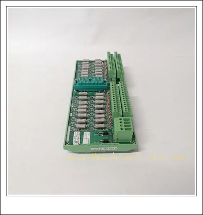
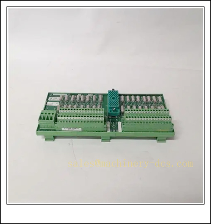
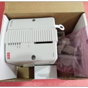
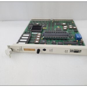
The TRICONEX 9000 is the next-generation triple modular redundant (TMR) safety instrumented system (SIS) controller, engineered for critical safety applications in oil & gas, refining, chemical, power, and energy industries. Built upon proven Triconex fault-tolerant technology, the 9000 platform delivers high availability, robust diagnostic coverage, and SIL 3 functional safety compliance. It supports hot-swappable I/O modules, seamless online maintenance, simplified configuration, and enhanced cybersecurity features. Designed to minimize spurious trips and avoid unplanned shutdowns, this safety controller provides reliable protection for process safety loops, emergency shutdown (ESD), fire & gas (F&G), and burner management systems (BMS).
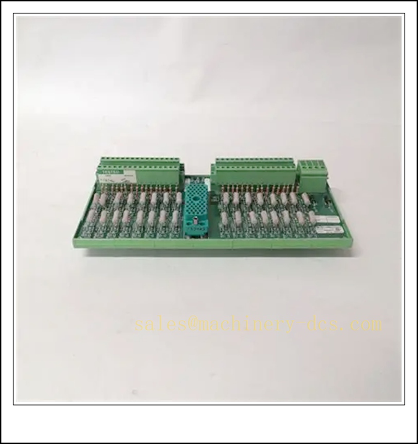
TRICONEX 9000
Key Technical Specifications
- Brand: TRICONEX
- Product Series: 9000 Series Safety Controller
- Architecture: Triple Modular Redundant (TMR)
- Safety Integrity Level: SIL 3 (IEC 61508)
- Voting Logic: 2-out-of-3 (2oo3)
- Hot Swap Support: Yes, modules can be replaced online without system shutdown
- Operating Temperature: 0 °C to +60 °C
- Storage Temperature: -40 °C to +85 °C
- Relative Humidity: 5% – 95%, non-condensing
- Backplane Communication: High-speed Triconex proprietary safety bus
- Diagnostic Coverage: >99% on-board self-test and loop diagnostics
- Configuration Software: TriStation 1131
- Cybersecurity: Supports access control, audit trail, firmware signature verification
- Mounting: Standard 19-inch industrial rack mounting
- EMC Compliance: IEC 61000 series
- Input / Output Type: Digital Input, Digital Output, Analog Input, Analog Output, HART-capable I/O
- Redundancy: Fully redundant power supplies, communication paths, and processor cores
Quality Control Procedure
- Visual & Label Inspection: Check cabinet, modules, connectors, front panels, and part marking for scratches, corrosion, or physical damage.
- Component Authenticity Verification: Confirm original factory components and screen non-genuine substitutions.
- Static Burn-in Test: Continuous powered aging under rated temperature to expose early failures.
- Full BIST Execution: Run built-in self-test for processors, I/O channels, backplane communication and fault indicators.
- TMR Voting Simulation Test: Validate 2oo3 redundant logic, fault isolation and fail-safe response.
- Signal Loop Calibration: Calibrate analog channels, verify HART communication if applicable.
- EMC Stress Screening: Subject unit to industrial electromagnetic interference simulation.
- Firmware & Configuration Check: Confirm official approved firmware revision and software compatibility.
- Serial Number & Test Log Archiving: Record SN, test data, tester information for full traceability.
- ESD Protected Packing: Anti-static packaging, shock-proof foam, moisture barrier before shipment.
Frequently Asked Questions (FAQ)
Q1: What applications is the TRICONEX 9000 used for?A1: It is widely used for ESD emergency shutdown, F&G fire and gas detection, BMS burner management, high-integrity pressure protection systems (HIPPS) and other SIL3 safety loops.
Q2: Can I swap modules online while the safety system is running?A2: Yes. All I/O and power modules support hot swap. You must follow approved site safety work permits and maintenance procedures.
Q3: Is TRICONEX 9000 compatible with older Tricon systems such as Tricon V10 / V11?A3: Native backward compatibility is limited. Interface modules are required for cross-series communication. Verify firmware and communication gateway models before project design.
Q4: What software do I use to program and download logic for the 9000 series?A4: TriStation 1131 is the official configuration, programming and diagnostic software for TRICONEX 9000.
Q5: What is the standard warranty term?A5: Standard warranty is 12 months from delivery date. Extended warranty and on-site support can be quoted separately.
Q6: Can the system continue running if one redundant channel fails?A6: Yes. The 2oo3 TMR architecture allows continuous safe operation with one failed channel, and triggers an alarm for maintenance.
Q7: Are spare modules ESD sensitive?A7: Highly sensitive. Always use ESD wrist straps, anti-static mats and shielding bags during handling.
Installation & Configuration Guide
- Pre-Install Preparation
- Confirm the cabinet location meets temperature, humidity, vibration and EMC site requirements.
- Prepare insulated tools, ESD protection kit, TriStation 1131 software, approved project safety logic, and part documentation.
- Inspect all controller racks, processors, I/O modules, power supplies and termination assemblies for damage.
- Mechanical Installation
- Mount the main rack into a standard 19-inch control cabinet, ensure sufficient ventilation clearance.
- Install backplane, redundant power supply units, processor modules and communication modules into designated slots.
- Insert I/O modules sequentially and lock front latches; route field wiring to termination boards following site drawings.
- Wiring Check
- Isolate field power and confirm all field loops are de-energized before termination.
- Separate safety signal cables from high-power cables to reduce interference.
- Verify grounding: dedicated protective earth and instrument ground as per Triconex installation manual.
- Power Up & Hardware Commissioning
- Apply power to redundant power supplies step by step.
- Observe LED status on each module; green indicates healthy status, red or amber indicates warning/fault.
- TriStation 1131 connects to the controller and automatically scans the hardware rack layout.
- Confirm all modules are recognized with correct part numbers and firmware revisions.
- Logic Download & Safety Validation
- Open the validated safety project in TriStation 1131.
- Download application logic to the TMR controller; complete compile check and forced variable audit.
- Perform point-to-point loop testing for all digital and analog I/O signals.
- Inject fault tests to verify voting function, alarm reporting and fail-safe action.
- Post-Commissioning & Handover
- Clear historical fault logs, record all serial numbers, firmware versions and test results in maintenance files.
- Set user access levels and audit trail functions for cybersecurity management.
- Submit system acceptance report to site operation team and switch the SIS to online running mode.
⚠ Important Notes
- Do not remove or insert modules without ESD protection.
- Any logic modification must follow site management of change (MOC) procedure.
- If persistent faults occur after installation, stop commissioning and contact your supplier for technical support.
Related TRICONEX Models & Part Number Recommendations (15 pcs)
- TRICONEX 9010 Main Processor Module
- TRICONEX 9011 Redundant Communication Module
- TRICONEX 9020 Digital Input Module
- TRICONEX 9021 Digital Output Module
- TRICONEX 9030 Analog Input Module (HART)
- TRICONEX 9031 Analog Output Module
- TRICONEX 9040 High-density DI Module
- TRICONEX 9050 Power Supply Module
- TRICONEX 9051 Rack Backplane
- TRICONEX 9060 Termination Board
- TRICONEX 9071 Remote Interface Module
- TRICONEX 9101 Expansion Chassis
- TRICONEX 9112 Communication Gateway
- TRICONEX 9200 FTA Terminal Assembly
- TRICONEX 9300 Safety Network Adapter

 Send an Email