
Description
Product Core Introduction
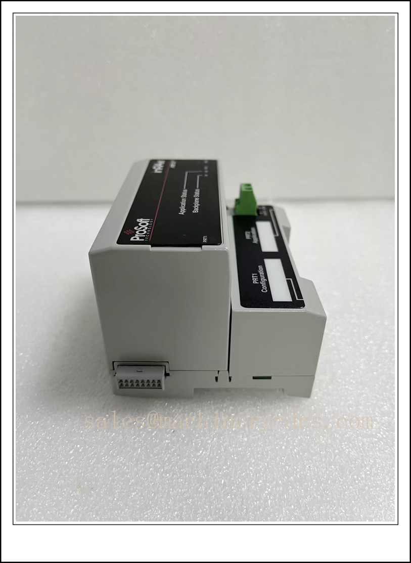
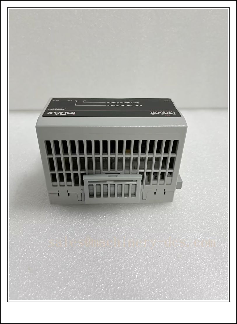
The ProSoft Technology MVI94-MCM is a dedicated high-performance Modbus communication interface module purpose-built for Rockwell Automation Allen-Bradley SLC 500 and MicroLogix PLC systems. As a specialized “protocol translator” inserted directly into the PLC 1746 series backplane rack, it offloads all Modbus protocol processing tasks from the PLC CPU, eliminating performance impact on core logic control scan cycles. It enables seamless bidirectional data exchange between Allen-Bradley PLCs and millions of field Modbus RTU/ASCII devices including smart transmitters, variable frequency drives, power meters, and industrial sensors, making it one of the most widely deployed protocol conversion solutions for legacy Rockwell automation system lifecycle extension projects worldwide.
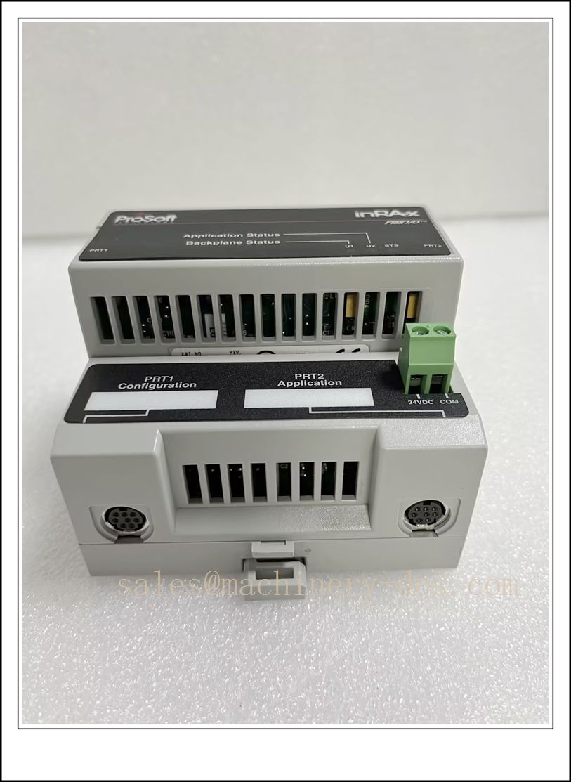
MVI94-MCM
Key Technical Specifications
| Parameter | Details |
|---|---|
| Manufacturer | ProSoft Technology (Rockwell Automation Encompass Partner) |
| Product Series | MVI94 SLC 500 Backplane Communication Module Family |
| Core Function | Independent Modbus RTU/ASCII Master/Slave protocol processing and data mapping |
| Host Compatibility | Allen-Bradley SLC 500 1746 series PLCs, MicroLogix 1000/1200/1500 controllers |
| Communication Interfaces | 2 × RS-232/RS-485 configurable serial ports; high-isolation MHI variant adds 1500 V AC galvanic isolation |
| Supported Protocols | Modbus RTU, Modbus ASCII, native DF1/DH+ Allen-Bradley backplane protocol |
| Max Slave Capacity | Supports up to 247 Modbus slave devices (address range 1-247) in master mode |
| Data Mapping | Full flexible mapping between Modbus registers and PLC N/B/T/C integer/bit/timer/counter files |
| Power Supply | 5 V DC direct power from PLC backplane, no external power adapter required |
| Operating Temperature Range | -40°C to +85°C, certified for harsh industrial field environments |
| Installation Format | Single-slot 1746 standard rack-mount design, no additional mounting brackets needed |
| Net Weight | Approximately 0.35 kg |
| Configuration Tool | ProSoft Configuration Builder (free official engineering software) |
Recommended Models from the Same Series
For users exploring compatible alternatives or extended functionality within ProSoft’s Modbus communication portfolio:
- MVI94-MCM-MHI: High-isolation enhanced variant with 1500 V AC reinforced galvanic isolation on RS-485 ports, eliminating ground loop damage risks in high-noise industrial environments
- MVI56-MCM: ControlLogix platform Modbus communication module, natively designed for Allen-Bradley 1756 ControlLogix PLC systems
- MVI69-MCM: CompactLogix platform Modbus interface module, optimized for 1769 CompactLogix small PLC system applications
- PLX32-EIP-MBTCP: Standalone EtherNet/IP to Modbus TCP gateway, supporting protocol conversion without occupying PLC rack slots
Safety Precautions Before Installation
- PLC Power Isolation: Always power off the SLC 500 PLC system completely before inserting or removing the module, to avoid backplane signal surge damage to the module’s communication processor.
- ESD Protection: Wear a properly grounded anti-static wrist strap during handling. The module’s high-speed DSP communication processor is extremely sensitive to electrostatic discharge, which can cause permanent unrepairable damage.
- Serial Wiring Compliance: Use shielded twisted-pair cables for all Modbus serial lines, strictly separate low-voltage signal wiring from high-power motor power cables to eliminate EMI communication interference.
- Address Conflict Prevention: Verify all Modbus slave device addresses are unique and no duplicate addresses exist on the same serial network before powering up the communication system.
- Documentation Review: Read the official ProSoft MVI94-MCM user manual and your PLC system wiring diagram before starting any installation procedure.
Hardware Installation Steps
- Pre-Installation Inspection: Unpack the new module and verify no physical transit damage exists. Confirm the part number MVI94-MCM exactly matches your system spare parts specification.
- Full PLC Power Down: Turn off the SLC 500 PLC main power supply, confirm zero residual voltage on the backplane slots with a calibrated multimeter.
- Insert the Module: Align the module with the guide rails of any empty single slot in the 1746 PLC rack, push it in smoothly until the backplane connector fully engages.
- Secure the Module: Tighten the two front panel mounting screws to lock the module firmly in place, preventing loose contact caused by long-term industrial vibration.
- Connect Serial Cables: Wire the Modbus serial network devices to the module’s front RS-232/RS-485 ports strictly following the official pinout definition.
- Basic Visual Check: Confirm no loose wires or foreign debris exist inside the PLC rack before restoring system power.
System Configuration Procedure
- Power-Up Test: Restore PLC system power, observe the module’s front-panel status LEDs, confirm the “Backplane Active” indicator lights up normally within 10 seconds.
- Connect Configuration Software: Launch ProSoft Configuration Builder on your engineering workstation, establish serial communication connection with the MVI94-MCM module.
- Define Polling List: Configure all Modbus slave device addresses, function codes, register ranges, and polling intervals according to your field device list.
- Complete Data Mapping: Define the bidirectional mapping relationship between Modbus register addresses and SLC 500 PLC N/B data files, configure 32-bit float byte order matching your field devices.
- Download Configuration: Compile the complete configuration project and download it permanently to the module’s non-volatile flash memory.
- PLC Ladder Logic Verification: Add the minimal required data exchange logic in your SLC 500 PLC ladder program, confirm the backplane high-speed data exchange channel is established normally.
Post-Installation Verification Points
- Self-Diagnostic Check: Confirm all front-panel status LEDs indicate normal operation, with zero active fault or communication error codes reported by the module.
- Serial Communication Test: Verify stable communication with every Modbus slave device on the network, confirm zero packet loss during 1 hour of continuous full-load polling testing.
- Data Consistency Validation: Compare the Modbus device raw register values against the corresponding PLC data file values, confirm 100% data consistency across all mapped addresses.
- Performance Impact Test: Monitor the SLC 500 PLC scan cycle time, confirm no noticeable scan cycle increase after the module is fully operational.
- Interference Immunity Test: Start nearby high-power variable frequency drives, confirm the Modbus communication link remains stable with no unexpected disconnections or data corruption.
- Maintenance Documentation Update: Record the module installation in the plant automation maintenance log, including the configuration file backup and all Modbus slave device address mapping records.
Application Scenarios & Key Features
- Application Scenarios:
- Manufacturing production lines: Seamless data integration between legacy SLC 500 PLCs and Modbus protocol variable frequency drives, power meters, and sensors
- Water & wastewater treatment plants: Protocol conversion for SLC 500 PLCs communicating with Modbus flow meters, level transmitters, and analyzer devices
- Oil & gas pipeline stations: Remote Modbus data acquisition for SLC 500 controlled compressor and pump unit monitoring systems
- Food & beverage processing facilities: Connecting legacy MicroLogix PLCs with Modbus temperature, pressure, and pH measurement instruments
- Key Features:
- Independent dedicated DSP processor completely offloads Modbus protocol processing from the PLC CPU, with zero negative impact on PLC logic control scan cycle performance
- Full master/slave dual-mode support, enabling the module to act as either Modbus master polling field devices or Modbus slave responding to external Modbus master requests
- 100% backward compatibility with all legacy SLC 500 PLC system architectures, supporting direct drop-in replacement for old ProSoft MVI series Modbus modules without modifying existing PLC rack wiring
- Ultra-wide -40°C to +85°C industrial extended temperature rating, ensuring reliable long-term operation in unconditioned industrial control cabinet environments
Frequently Asked Questions (FAQs)
Q1: Can MVI94-MCM work with my existing SLC 5/04 PLC system?
A: Yes, it is fully compatible with all SLC 500 series PLC models including SLC 5/01, 5/02, 5/03, 5/04, and 5/05, requiring no PLC firmware upgrade.
Q2: What is the maximum Modbus serial communication baud rate supported?
A: The module supports standard Modbus baud rates up to 115200 bps, fully meeting high-speed Modbus RTU communication requirements for most industrial field devices.
Q3: Do I need to write complex Modbus protocol parsing logic in the PLC ladder program?
A: No, all Modbus protocol processing is handled independently by the module. You only need to perform simple read/write operations on the mapped PLC data files in your ladder logic.
Q4: What is the typical service life of this module under normal operating conditions?
A: With proper industrial environment protection, the module has a rated design service life of over 10 years for continuous operation in factory automation facilities.

 Send an Email