
Description
Honeywell FS‑CPCHAS‑0001 Control Processor Chassis
Title
Honeywell FS‑CPCHAS‑0001 19‑Inch Controller Chassis for Safety Manager / FSC SIS System
Meta‑Description
Honeywell FS‑CPCHAS‑0001 is a 4U 19‑inch control processor chassis for Honeywell Safety Manager SIS, integrated with CPB‑0001 controller backplane, supports redundant / non‑redundant CPU installation, provides internal safety‑bus interconnection and power distribution, TÜV‑certified SIL3 system‑level mechanical carrier for petrochemical ESD safety instrumented racks。
Product Core Overview
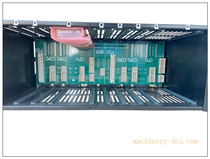
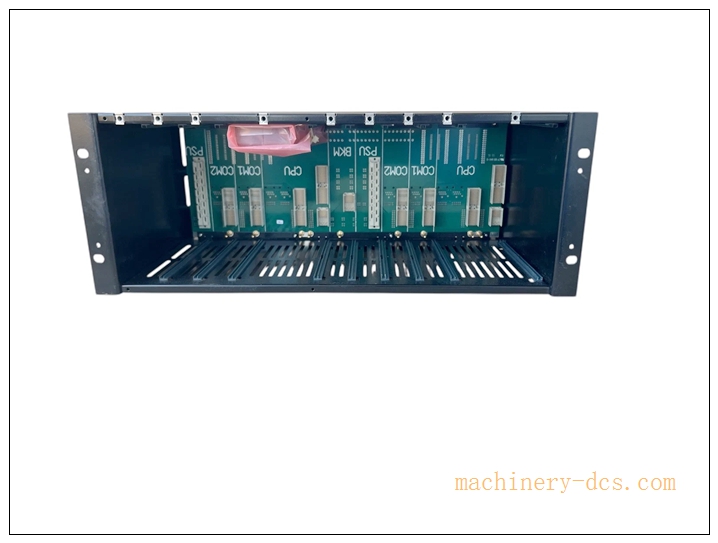
FS‑CPCHAS‑0001 is the dedicated controller chassis for Honeywell Safety Manager (FSC) safety‑instrumented system, composed of metal housing and matching CPB‑0001 controller backplane. It is used to install safety processor modules, FC‑BKM‑001 battery‑key‑switch module and related controller‑side interface modules. It supports both redundant dual‑CPU and single‑CPU non‑redundant architecture.
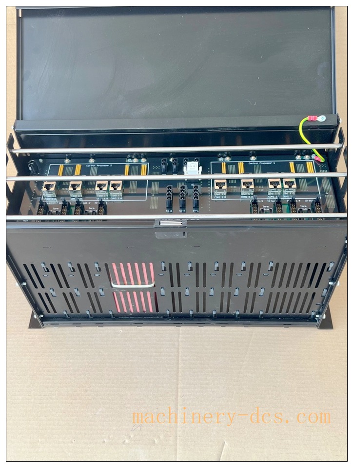
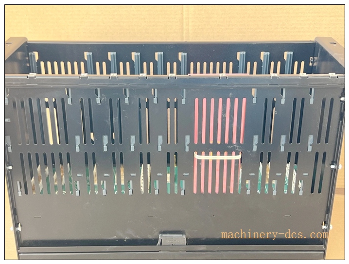
Modules are inserted from front panel and fastened by quarter‑turn captive fasteners. The rear side adopts a flip‑type magnetic cover plate; after opening, you can see backplane connectors and three‑layer cable management guide grooves for 24VDC power signal, communication cable and 5V watchdog cable respectively. The backplane realizes safety‑bus signal routing, grounding and internal power distribution. This chassis is generally installed in the upper part of the cabinet, matched with IO chassis for I/O module installation, widely used in oil‑gas and chemical SIL3 ESD interlock projects.
FS-CPCHAS-0001
Main Technical Specifications
| Item | Parameter |
|---|---|
| Part Number | FS‑CPCHAS‑0001 |
| Module Type | Controller Chassis (including CPB‑0001 backplane) |
| Compatible System | Honeywell Safety Manager / FSC SIS |
| Mounting | Standard 19‑inch rack‑mount, 4U (4HE) |
| Dimensions(W×H×D) | 482.6 mm × 177 mm × 280 mm |
| Weight | 5.8 kg |
| Supported Architecture | Redundant dual‑CPU / non‑redundant single‑CPU |
| Built‑in Backplane | CPB‑0001 controller backplane, safety‑bus routing, dual 5V power rail |
| Cable Management | Rear 3‑bar cable routing structure |
| Cooling Mode | Passive natural convection cooling, no built‑in fan |
| Enclosure Protection | IP20, for indoor cabinet installation |
| Safety Certification | TÜV SIL3, CE, UL, CSA, FM safety approval |
| Operating Temperature | 0 °C ~ +60 °C |
| Storage Temperature | −40 °C ~ +85 °C |
| Relative Humidity | 5‑95 % non‑condensing |
Quality Control Procedures
- Visual & Mechanical Incoming Inspection: Inspect chassis metal shell, backplane PCB, connectors, locking mechanism and label printing; record serial number for full‑lifecycle traceability.
- Backplane Continuity & Isolation Test: Test each backplane slot signal pin continuity, insulation and isolation performance.
- Mechanical‑fit Test: Verify smooth insertion and locking of processor module, FC‑BKM‑001 and other controller‑side modules.
- Ground‑path Verification: Check chassis‑backplane protective‑ground continuity, satisfy SIS safety grounding requirements.
- Cable‑accessory Matching Inspection: Verify rear flip‑cover and cable‑management bar assembly reliability.
- Environmental Stress Screening: Temperature‑cycle test for whole chassis assembly.
- Final End‑of‑Line Validation & Archiving: Complete full‑function inspection; archive test records bound to unit serial‑number before factory release.
Related Brand Model Recommendations
- IOCHAS‑0001S: I/O chassis, for installation of FC‑SDIL‑160824VDC, FC‑SDO‑0824, FC‑SAI‑1620M and other I/O modules。
- FC‑BKM‑001: Battery and key‑switch module, must be installed in FS‑CPCHAS‑0001 controller chassis.
- FC‑PSU‑UNI2450U: SIS system external 24VDC power‑supply unit.
- Matching Controller: Honeywell Safety Manager CPU processor module.
- System Accessories: 19‑inch cabinet, safety‑rated screened cables, ground‑bus bar.
FS-CPCHAS-0001
Frequently Asked Questions (FAQ)
Q1: Can I install I/O modules such as FC‑SDO‑0824 inside FS‑CPCHAS‑0001? A: No. FS‑CPCHAS‑0001 is controller chassis, only for CPU, FC‑BKM‑001 and controller‑interface modules. All digital / analog I/O modules must be installed in IOCHAS‑0001S I/O chassis。
Q2: What does FS‑CPCHAS‑0001 contain in delivery scope? A: Metal housing + CPB‑0001 controller backplane; processor, FC‑BKM‑001 and other functional modules are not included and need separate ordering。
Q3: Does chassis support hot‑swap of internal modules? A: Module hot‑plug is mechanically possible. For running SIS system, safety‑bypass procedure must be strictly followed before replacing CPU or FC‑BKM‑001 module.
Q4: What is the difference between FS‑CPCHAS‑0001 and IOCHAS‑0001S? A: FS‑CPCHAS‑0001: controller chassis, for CPU and BKM module; IOCHAS‑0001S: I/O chassis, dedicated for all I/O input/output modules。
Q5: Can I repair chassis and backplane on‑site? A: No. Unauthorized disassembly and modification will void SIL certification. Return defective unit to authorized service‑centre.
Installation & Configuration Guide
Pre‑Installation
- Inspect chassis for transit damage. Confirm part‑number FS‑CPCHAS‑0001 and serial‑number match purchase‑order, confirm CPB‑0001 backplane intact.
- Prepare 19‑inch cabinet, Safety Manager CPU processor module, FC‑BKM‑001 module, 24VDC power supply, safety‑system screened cables.
- Review project SIS drawing: confirm cabinet layout, controller chassis is installed in upper cabinet position, I/O chassis is arranged below.
Mechanical Installation
- Fix FS‑CPCHAS‑0001 to standard 19‑inch cabinet with M4 screws, reserve enough upper‑lower ventilation space for passive cooling.
- Insert safety processor module and FC‑BKM‑001 module into corresponding slots from front panel, tighten quarter‑turn captive fasteners.
Important: Do not force insertion; pay attention to module slot‑key‑position to avoid connector damage.
Electrical Wiring
- Open rear magnetic flip‑cover of chassis, route 24VDC power cables, communication cables and watchdog cables respectively to three‑layer rear cable‑management bars, fix cable ties.
- Complete cabinet protective‑ground connection for chassis, strictly follow SIS grounding specification.
- Connect 24VDC power supplied by FC‑PSU‑UNI2450U to controller backplane power‑terminal.
System Configuration & Commissioning
- After completing all module installation and wiring, power‑on the SIS system.
- Launch Honeywell Safety Builder configuration‑software, connect to Safety Manager controller, verify all modules in controller chassis are correctly identified.
- Cooperate with I/O chassis to complete whole‑hardware‑configuration download, verify system no hardware fault alarm.
- Check chassis ventilation and temperature under full‑load running condition, confirm temperature within specification range.
- Save full‑project‑configuration‑backup‑file, chassis enters normal SIS safety‑interlock running state.

 Start Chat


 Send an Email


