
Description
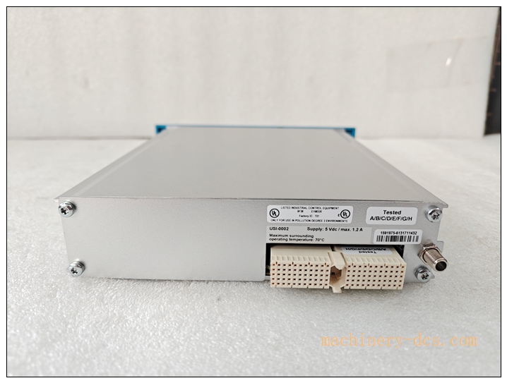
Honeywell FC‑USI‑0002 Universal Safety Interface Module
Title
Honeywell FC‑USI‑0002 Universal Safety Interface (USI) Communication Module for Safety Manager / FSC SIS System
Meta‑Description
Honeywell FC‑USI‑0002 is universal safety communication interface module for Honeywell Safety Manager SIS, provides isolated Ethernet and serial communication channels, handles non‑safety communication off‑load from QPP CPU, supports Modbus‑TCP, Modbus‑RTU, used for connecting SIS to DCS, HMI and third‑party systems, installs in FS‑CPCHAS‑0001 controller chassis, TÜV SIL3 certified。
FC‑USI‑0002
Main Technical Specifications
| Item | Parameter |
|---|---|
| Part Number | FC‑USI‑0002 |
| Module Type | Universal Safety Interface Communication Module |
| Compatible System | Honeywell Safety Manager / FSC SIS |
| Mounting Slot | FS‑CPCHAS‑0001 controller chassis |
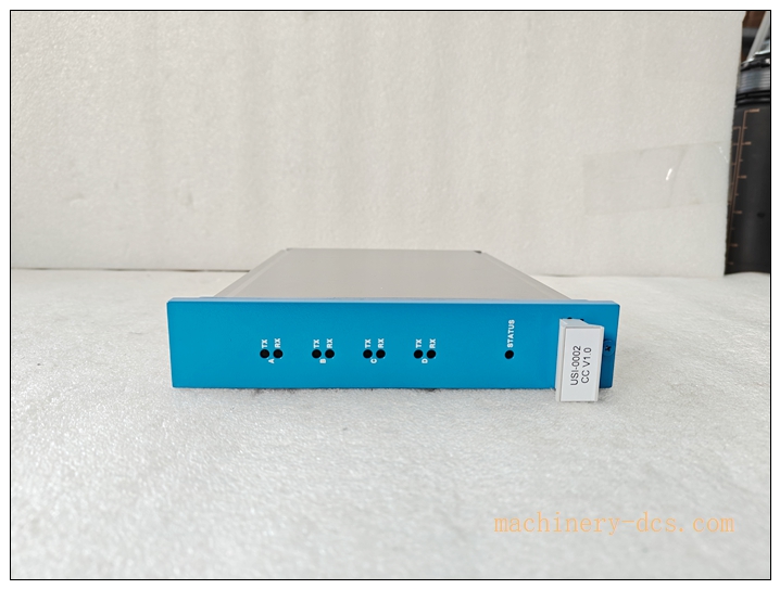
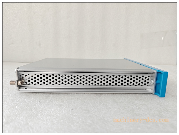
| Physical Ports | 2 × 10/100Mbps RJ45 Ethernet;2 × Serial (RS232 / RS485) |
| Supported Protocols | Modbus‑TCP, Modbus‑RTU |
| Memory | Flash 8MB;ECC‑SRAM 8MB;Shared RAM 256KB (inter‑communicate with QPP CPU) |
| Internal Power | 5VDC ±5%, Max 1.2A |
| LED Indicators | Module OK, Fault, Channel activity status LEDs |
| Safety Certification | TÜV SIL3, IEC 61508 / IEC 61511, CE, UL/cULus, FM |
| Conformal Coating | CC variant available |
| Operating Temperature | −5 °C ~ +60 °C |
| Storage Temperature | −40 °C ~ +85 °C |
| Relative Humidity | 5‑95 % non‑condensing |
| Weight | 0.7 kg |
| Hot‑Swap | Mechanically hot‑pluggable; safety‑bypass procedure mandatory for live‑system replacement |
Quality Control Procedures
- Visual & Mechanical Incoming Inspection: Inspect PCB, front‑panel LED, RJ45 / serial connectors, gold‑plated backplane connector, marking; record serial‑number for full‑lifecycle traceability.
- Backplane Interface Continuity Test: Verify pin‑level continuity, insulation and isolation for FS‑CPCHAS‑0001 backplane connector.
- Shared‑RAM Data‑exchange Test: Validate high‑speed data exchange between FC‑USI‑0002 and FC‑QPP‑000x processor.
- Communication Channel Function Test: Test Ethernet & serial ports, verify Modbus‑TCP / Modbus‑RTU send‑receive performance.
- Redundant Communication Test: Dual‑USI redundant pair data switch‑over test.
- Diagnostic‑Fault‑report Test: Simulate port failure, module hardware fault, confirm fault alarm reported to SIS controller.
- Environmental Stress Screening: Temperature‑cycle test across full operating‑temperature range.
- EMC Compatibility Test: Industrial electromagnetic‑interference compliance test.
- Final End‑of‑Line Validation & Archiving: Complete full‑function test suite; archive test‑records bound to unit serial‑number before factory release.
Related Brand Model Recommendations
- FS‑CPCHAS‑0001: Controller chassis for FC‑USI‑0002, QPP‑CPU and FC‑BKM‑001.
- FC‑QPP‑0001 / FC‑QPP‑0002: Quad redundant safety processor pack.
- FC‑BKM‑001: Battery & key‑switch module.
- FC‑IOCHAS‑0001S: Non‑redundant I/O chassis.
- FC‑SDIL‑160824VDC: Loop‑monitored safety digital‑input module.
- FC‑SDO‑0824: Safety solid‑state digital‑output module.
- FC‑SAI‑1620M: Conformal‑coated safety analog‑input module.
- FC‑PSU‑UNI2450U: SIS system 24VDC power‑supply unit.
Frequently Asked Questions (FAQ)
Q1: Where should FC‑USI‑0002 be installed? A: Must install inside FS‑CPCHAS‑0001 controller chassis, cannot mount into I/O chassis FC‑IOCHAS‑0001S.
Q2: What is the core value of USI module? A: Off‑load all external communication traffic from safety QPP‑CPU. Realize isolation between safety‑voting logic and non‑safety external network, satisfy IEC‑61508 functional‑safety separation requirement.
Q3: Can I run dual FC‑USI‑0002 for communication redundancy? A: Yes. When using dual redundant QPP‑CPU(A/B), install one USI for each CPU, realize redundant communication path.
Q4: Can FC‑USI‑0002 execute safety logic? A: No. It is pure communication interface. Safety logic calculation and voting is fully completed by FC‑QPP‑0001/0002 processor.
Q5: Can I hot‑swap FC‑USI‑0002 on running SIS rack? A: Mechanically hot‑pluggable. If single‑USI configuration, communication will drop during replacement, safety logic keeps running. Follow Honeywell maintenance procedure strictly.
Q6: Can I repair module on‑site? A: No. Unauthorized disassembly voids SIL certification and warranty. Return defective unit to authorized service‑centre.
FC‑USI‑0002
Installation & Configuration Guide
Pre‑Installation
- Inspect module for transit damage. Confirm part‑number FC‑USI‑0002 and serial‑number match purchase‑order.
- Confirm FS‑CPCHAS‑0001 controller chassis, FC‑QPP‑000x CPU, FC‑BKM‑001 module are complete.
- Prepare Ethernet cables, serial communication cables, Safety Builder engineering software.
- Review SIS drawing: confirm single‑USI or dual‑redundant USI architecture definition.
Mechanical Installation
- Insert FC‑USI‑0002 into target slot of FS‑CPCHAS‑0001 controller chassis from front panel, tighten quarter‑turn captive fasteners.
Important: For dual‑redundant CPU architecture, install one FC‑USI‑0002 for each A/B processor. Do not force insertion; observe slot key‑position to avoid connector damage.
Electrical Wiring
- Complete chassis protective‑ground connection per SIS grounding specification.
- Connect Ethernet / serial cables to front‑panel ports, route communication cables separate from high‑power cables.
- Connect safety‑bus cable between controller chassis and I/O chassis.
- 24VDC power supplied by FC‑PSU‑UNI2450U to controller chassis backplane.
System Configuration & Commissioning
- After finishing hardware installation, power‑on SIS system. Observe FC‑USI‑0002 front‑panel LED status.
- Launch Honeywell Safety‑Builder software, connect to processor, confirm FC‑USI‑0002 is correctly recognized.
- Configure communication parameters: IP address, Modbus register mapping, serial baud‑rate & protocol settings inside project.
- Download updated hardware & communication configuration to SIS controller.
- Establish connection with DCS/HMI/third‑party Modbus devices, verify data read‑write consistency.
- Simulate USI module / port fault condition, verify SIS generates correct diagnostic alarm and event log.
- For dual‑USI redundant setup, test communication bumpless switch‑over between primary and standby USI path.
- Save full‑project‑configuration‑backup‑file, system enters formal SIL3 safety‑interlock running state.

 Start Chat


 Send an Email


