
Description
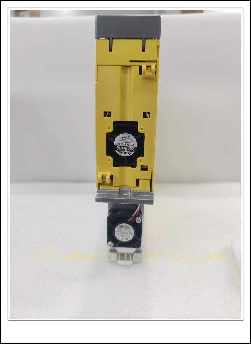
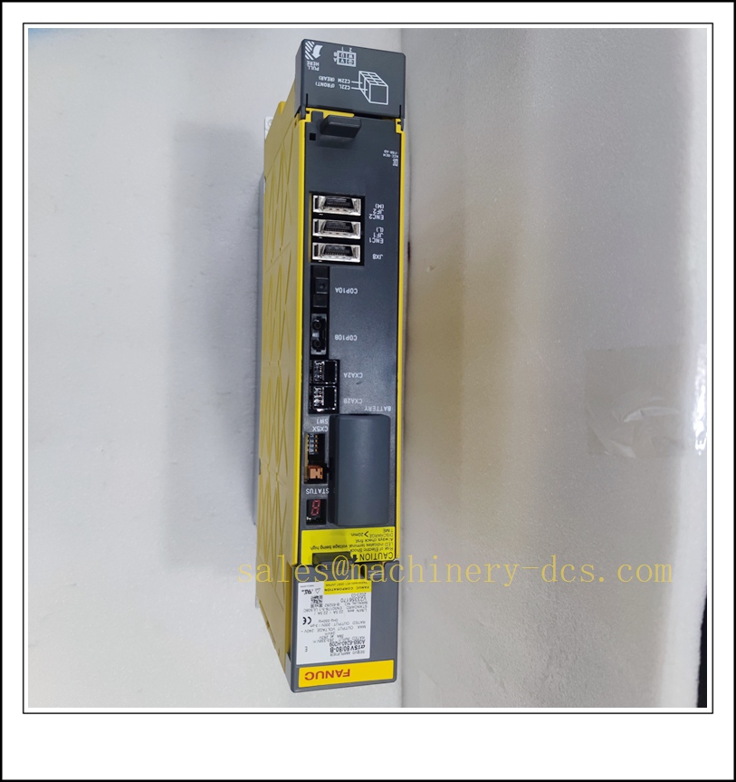
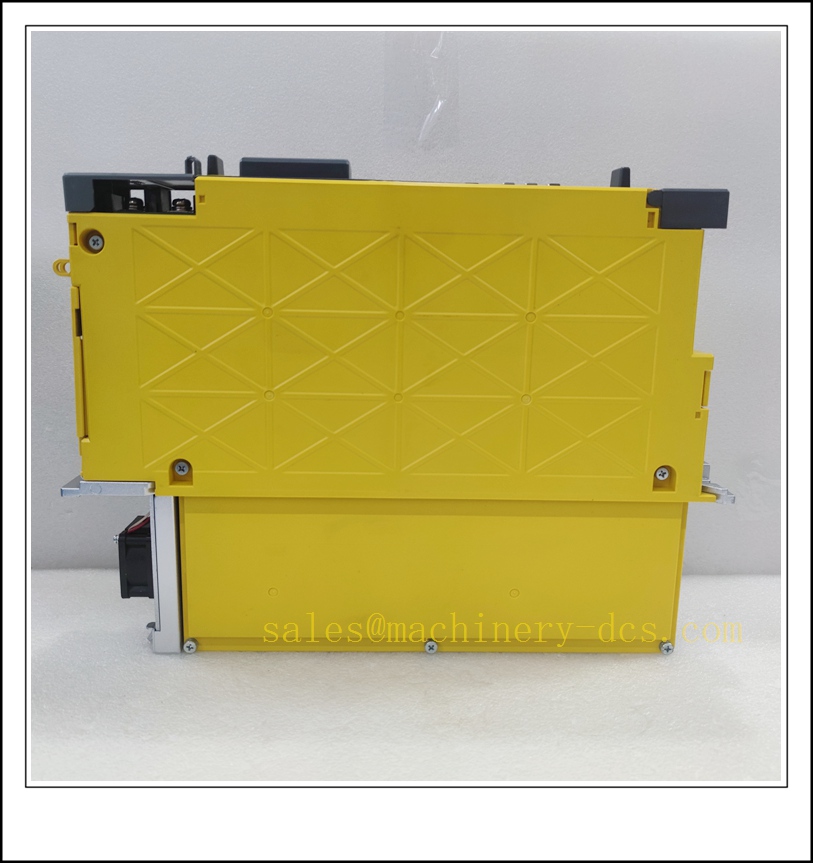
FANUC A06B-6240-H209 αiSV 80/80-B Dual Axis Servo Amplifier Module
Product Description
The A06B-6240-H209 is a dual-axis digital servo amplifier belonging to FANUC Alpha i series, designated αiSV 80/80-B. It delivers high-performance position, speed and torque closed-loop control for two independent servo axes. This unit adopts high-speed DSP control algorithm, built-in regenerative energy absorption circuit and comprehensive hardware protection functions. It communicates with FANUC CNC or robot controller via FANUC proprietary high-speed servo fiber link. Widely used as auxiliary axis drive for 7th/8th external axes of FANUC robots, as well as synchronized motion control for CNC machine tools. It supports high dynamic response and high positioning accuracy for precision motion applications.
Technical Specifications
- Brand: FANUC
- Part Number: A06B-6240-H209
- Model: αiSV 80/80-B
- Product Type: Dual Axis Servo Amplifier
- Number of Controlled Axes: 2 axes
- DC Bus Input: 283 ~ 339 VDC
- Rated Output: 200 VAC 3-phase, Max 240 VAC
- Continuous Output Current: 80 A per axis
- Peak Output Current: 160 A per axis
- Max Output Frequency: 550 Hz
- Control Mode: Digital closed-loop servo control
- Feedback Interface: FANUC serial encoder (αi pulse coder)
- Communication: FANUC optical fiber servo link
- Cooling: Forced air cooling with built-in fan
- Protection: Overcurrent, overvoltage, undervoltage, overheat, short-circuit, encoder disconnection, dynamic brake fault
- Ambient Operating Temperature: 0 °C ~ +55 °C
- Storage Temperature: -20 °C ~ +70 °C
- Relative Humidity: 5% ~ 95%, non-condensing
- Mounting: Vertical rack mounting inside electrical cabinet
- Certification: CE, UL, KCC
- Approximate Weight: 7.5 kg
A06B-6240-H209
Application Scenarios
- External 7th / 8th auxiliary axis of FANUC R-30iB / R-30iB Plus robot systems, including positioners, rotary tables and linear tracks
- High-speed machining centers, vertical and horizontal CNC lathes requiring dual synchronized servo axes
- Automated production transfer lines, gantry automation and multi-axis synchronous positioning equipment
- Precision grinding machines, die-sinking EDM and high-precision special CNC machinery
- Automotive welding, handling robot external servo positioner systems
- Aerospace composite machining equipment with multi-axis coordinated motion
- Machine tool retrofit and upgrade projects for existing FANUC 30i-B / 0i-MF CNC platforms
- Spare replacement and maintenance of FANUC Alpha i servo drive systems
8 Related FANUC Model Recommendations
- A06B-6240-H206 – αiSV 40/40-B Dual Axis Servo Amplifier
- A06B-6240-H207 – αiSV 60/60-B Dual Axis Servo Amplifier
- A06B-6240-H210 – αiSV 100/100-B Dual Axis Servo Amplifier
- A06B-0265-B605 – FANUC αiS 80/4000 Servo Motor
- A06B-0243-B605 – FANUC αiF 22/3000 Servo Motor
- A06B-6200-H011 – FANUC αiPS Power Supply Module
- A06B-6141-H003 – Single Axis αiSV Servo Amplifier
- A02B-0338-B502 – FANUC 31i-B CNC Main Unit
Compatibility & Installation Pitfalls
Compatibility
- Designed for FANUC R-30iB / R-30iB Plus robot controllers and 30i-B / 0i-MF CNC systems; not compatible with older 16i/18i/21i-B platforms without firmware upgrade.
- Matched with FANUC αiS and αiF series 200V class serial encoder servo motors; motor capacity must match amplifier rating.
- Requires paired FANUC αiPS power supply module to provide DC bus voltage; cannot work as a standalone power source.
- Uses FANUC optical fiber servo link; incompatible with analog pulse or Modbus external control.
- Encoder cable and power cable must be FANUC specified shielded cables; generic wiring may cause feedback loss or EMI alarm.
- Firmware version of CNC/robot controller must support αiSV-B series drives; mismatched firmware leads to link alarm.
Installation Pitfalls
- High DC bus voltage remains on internal capacitors long after power disconnection. Always wait for capacitor discharge before touching terminals to prevent electric shock.
- DC bus positive and negative terminals must never be reversed; reverse wiring will immediately destroy the power stage.
- The amplifier must be mounted vertically with sufficient clearance above and below for cooling airflow; blocked ventilation triggers overheat alarm (OH).
- Power cables and encoder feedback cables shall be routed separately. Shielding must be single-point grounded at the cabinet side to reduce electromagnetic interference.
- Do not hot-plug fiber optic connectors, encoder connectors or motor power terminals while the system is powered; this may damage communication chips or encoder circuits.
- The built-in cooling fan is a consumable part. If the fan stalls, shut down immediately; continuous operation without cooling will burn the power module.
- For long-term storage over 3 months, perform low-voltage pre-energization for 30 minutes before commissioning to recover electrolytic capacitors.
- Never short-circuit emergency stop and safety gate interlock circuits; safety signals are mandatory for robot auxiliary axis and machine tool applications.
A06B-6240-H209
Standard Operating Procedure (SOP)
SOP for A06B-6240-H209 Servo Amplifier Inspection, Installation and Functional Test
- Pre-Installation Inspection Examine the unit for physical damage, cracked casing, bent terminals or contaminated circuit boards. Confirm the part number A06B-6240-H209. Verify compatibility with the CNC or robot controller firmware, αiPS power supply and paired servo motors. Review electrical schematics, DC bus wiring and safety interlock layout. Apply lockout-tagout on the main incoming power circuit.
- Rack Installation Mount the amplifier vertically in the control cabinet. Maintain required airflow clearance. Secure the unit with mounting screws. Connect DC bus terminals from αiPS power supply, motor power terminals and serial encoder feedback connectors. Route shielded cables in separate trunking away from high-power VFD cables, and implement cabinet EMC grounding as per FANUC specification.
- Configuration and Parameter Setup Power on the controller with no motor load connected. Establish fiber servo link between the amplifier and CNC/robot controller. Perform servo motor parameter auto-recognition. Set axis assignment, electronic gear ratio, soft limit and safety parameters according to mechanical drawing. Save parameter backup to CNC memory or external storage. Resolve servo link or encoder alarm codes before loading the mechanical load.
- Channel and Dynamic Test Execute JOG movement for each of the two axes under no-load condition. Verify normal speed regulation and encoder position feedback. Test emergency stop and safety gate interlock to confirm dynamic brake activation. Check regeneration function during deceleration. Record alarm responses for overtravel, encoder loss and overcurrent in maintenance log.
- Mechanical Load Commissioning Couple the amplifier to mechanical load. Run low-speed test movement, then gradually increase speed and acceleration to rated operating conditions. Tune servo gain to suppress vibration and improve positioning stability. Confirm no abnormal noise, heating or position deviation during synchronized motion. Verify that faults trigger diagnostic alarms only without uncontrolled axis runaway.
- Return to Production Service Clear alarm latches and acknowledge diagnostic messages. Remove lockout-tagout. Monitor axis load current, amplifier temperature and encoder signal quality through the observation period. Notify production that the dual-axis servo amplifier is commissioned and ready for operation.
- Periodic Maintenance and Replacement During scheduled downtime, inspect fan operation, terminal torque, cable shielding and capacitor health. Perform load test and emergency stop proof-test according to machine maintenance schedule. If persistent unrecoverable power stage or link faults occur, lock out main power before amplifier replacement. After replacement, reload servo parameters, re-identify motors and complete full motion test before releasing to production.

 Start Chat


 Send an Email


