
Description
Allen‑Bradley 1756-L72, ControlLogix 5570 Controller, 4MB User Memory
2. Core Product Introduction
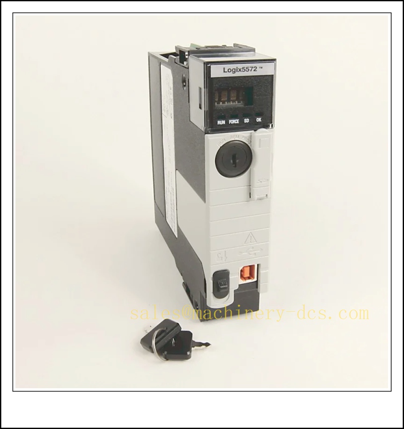
1756-L72
3. Main Technical Specifications
| Item | Parameter |
|---|---|
| Catalog No. | 1756-L72 |
| Series | ControlLogix 5570 |
| User Memory | 4 MB |
| I/O Memory | 0.98 MB |
| Local Port | USB Type‑B for programming |
| Non‑volatile Storage | SD card slot (1784-SD1 supplied standard, max 2GB SD) |
| Energy Storage | 1756-ESMCAP capacitor module (no lithium battery) |
| Backplane Draw | 800mA @ 5.1V DC, 5mA @1.2V DC |
| Power Dissipation | 2.5 W |
| Max CIP Motion Axes | Up to 8 axes |
| Redundancy Support | Enhanced redundancy compatible |
| Operating Temperature | 0 °C ~ +60 °C |
| Storage Temperature | -40 °C ~ +85 °C |
| Humidity | 5%–95% RH, non-condensing |
| Mounting | 1756 ControlLogix chassis backplane |
| Weight | ~0.91 kg |
| Certifications | cULus, CE, KC |
| Lifecycle Status | Active Mature |
| Standard Warranty | 1 year |
4. Quality Control Procedure
- Visual & Label Inspection: Verify original Rockwell label, catalog number 1756-L72, serial number, key switch, USB port, SD slot and edge connector; no bent pins, scratches or corrosion.
- Backplane Power Boot Test: Install on test chassis, power up, confirm RUN/FAULT LED sequence, no overheating or abnormal current draw.
- USB Programming Port Test: Connect Studio5000 PC via USB, verify controller upload/download and online edit access.
- SD Card & ESM Function Test: Test project save/restore to SD card; verify capacitor ESM holds image during brief power loss.
- Backplane Communication Test: Scan chassis I/O and comm modules, confirm backplane handshake and tag communication.
- Logic Runtime Test: Download test logic, force tags, monitor execution and fault response.
- Key Switch & Mode Check: Validate RUN / PROGRAM / REM mode switching via front key switch.
- Firmware Validation: Confirm firmware revision matches customer project compatibility requirement.
- LED Indicator Check: Verify RUN, FAULT, FORCE, OK indicators behave correctly.
- Packaging & Traceability: Static bag + foam packaging, serial-number QC report before shipment.
5. Frequently Asked Questions (FAQ)
A1: 1756-L72 is standard general-purpose controller. 1756-L72S is GuardLogix safety controller with SIL2 / SIL3 safety memory partition for safety instrumented applications. They are not interchangeable without safety project review.
A2: No. It requires separate 1756 EtherNet/IP modules (1756-EN2T, EN3TR etc.) for network connection. L8xE series have embedded Ethernet.
A3: Studio5000 Logix Designer (RSLogix 5000 successor). Firmware version must match Studio5000 revision.
A4: Yes, it supports ControlLogix enhanced redundancy system with 1756-RM2 redundancy module and matching comm modules.
A5: ESM capacitor preserves volatile tag data and writes to SD card on power loss; eliminates lithium battery replacement and disposal concerns.
A6: Logic project can be migrated, but chassis, communication strategy and network topology need review; it is not a plug-and-play drop-in replacement.
6. Installation & Configuration Guide
- Pre-install Preparation: ControlLogix chassis, 1756 power supply, Studio5000 software, SD card, ESM capacitor module, key.
- Chassis Slot Planning: Assign CPU slot, reserve slots for I/O and communication modules, follow redundancy rules if redundant.
- Module Insertion: Power off chassis or follow hot-swap procedure, seat 1756-L72 firmly into backplane slot and lock.
- ESM & SD Installation: Fit 1756-ESMCAP capacitor and SD card into front slots.
- Power Up: Energize rack power, confirm controller boots without major fault.
- Connect PC via USB: Establish Studio5000 online connection, verify controller identity and firmware.
- Download Application: Download validated program, tags, data types and controller configuration.
- I/O & Network Configuration: Configure EtherNet/IP modules, I/O modules, motion axes and controller tags.
- Online Commissioning: Force inputs, test outputs, verify motion and alarm functions; confirm redundancy sync if redundant pair.
- Backup: Save source project, store runtime backup to SD and offline archive; record firmware revision and serial number.
Warning: Hot-swap is supported but avoid removing controller during critical production cycles. Always back up project before firmware upgrade or module replacement.
7. Related ControlLogix 5570 / 5580 Models & Accessories (15 pcs)
| Model | Order Number | Description |
|---|---|---|
| 2MB Controller | 1756-L71 | ControlLogix 5570, 2MB memory |
| 8MB Controller | 1756-L73 | ControlLogix 5570, 8MB memory |
| GuardLogix Safety CPU | 1756-L72S | SIL capable safety controller 4MB |
| EtherNet/IP Module | 1756-EN2T | Dual copper EtherNet/IP comm module |
| Enhanced Redundancy Module | 1756-RM2 | Redundancy module for L7x |
| ESM Capacitor Module | 1756-ESMCAP | Standard energy storage capacitor |
| SD Memory Card | 1784-SD2 | 2GB SD card for Logix controller |
| 1756 Chassis | 1756-A10 | 10-slot ControlLogix chassis |
| ControlLogix Power Supply | 1756-PA72 | AC input rack power supply |
| 1756-L82E | 1756-L82E | 5580 controller with embedded Ethernet |
| 1756-L83E | 1756-L83E | 5580 higher performance CPU |
| Digital Input Module | 1756-IB16 | 16-point 24VDC DI |
| Digital Output Module | 1756-OB16E | 16-point 24VDC DO |
| Analog Input Module | 1756-IF8 | 8-channel 4-20mA AI |
| Analog Output Module | 1756-OF8 | 8-channel AO module |

 Send an Email