
Description
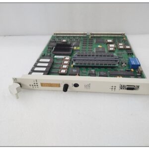
Allen‑Bradley 1715‑AENTR EtherNet/IP Redundant Adapter | Industrial Automation Spare Part
Product Overview
The Allen‑Bradley 1715‑AENTR is an EtherNet/IP communication adapter for the Rockwell 1715 fault‑tolerant redundant I/O system. It serves as the network gateway linking ControlLogix / GuardLogix controllers to 1715 series redundant I/O racks over EtherNet/IP. Deployed in duplex paired configuration, it delivers bumpless switchover for high‑availability control loops and supports SIL 2 rated applications.Commonly used in oil & gas, refining, power generation and pipeline industries, this adapter is a critical spare for safety and process control systems, reducing plant downtime during network adapter failure. It must be installed on the dedicated 1715‑A2A dual adapter base and can drive up to 24 I/O modules per adapter pair.
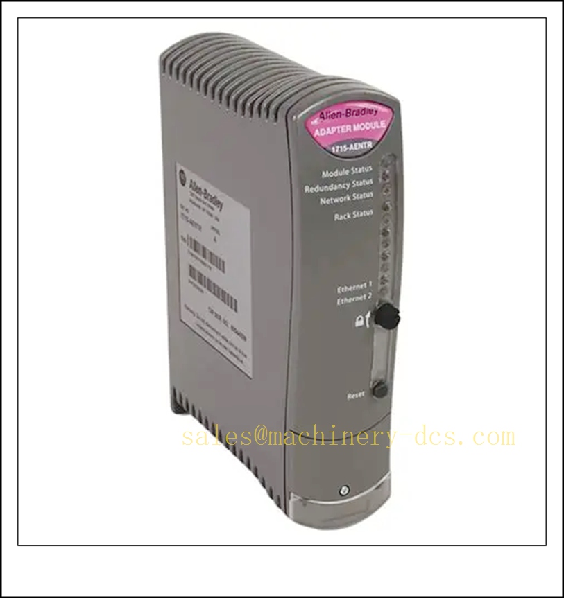
1715-AENTR
Key Technical Specifications
| Item | Parameter |
|---|---|
| Catalog No. | 1715‑AENTR |
| Product Type | EtherNet/IP Redundant I/O Adapter |
| Compatible Controller | ControlLogix, GuardLogix |
| Supported I/O Family | Bulletin 1715 Redundant I/O Modules |
| Communication Protocol | EtherNet/IP (CIP) |
| Ethernet Ports | Dual-port redundant Ethernet |
| Required Base | 1715‑A2A (2-slot adapter backplane) |
| Max I/O Modules per Pair | 24 units |
| Supply Voltage | 18 ~ 32 V DC |
| Backplane Current | 380 mA typical |
| Power Dissipation | Max 8 W |
| Operating Temperature | 0 °C ~ +60 °C |
| Storage Temperature | -40 °C ~ +85 °C |
| Relative Humidity | 5% ~ 95 %, non‑condensing |
| Insulation Test | 500 VAC, 60 s |
| Safety Rating | SIL 2 capable when configured per Rockwell safety manual |
| Mounting | DIN rail cabinet installation, IP20 |
| Origin | USA |
| Certification | CE, UL |
Quality Control Procedure
- Visual & Label Inspection: Check housing, Ethernet ports, backplane connector, LED indicators and laser part marking; inspect ESD packaging.
- Power Bench Test: Apply 24 VDC supply, verify power LED and no short circuit.
- Network Communication Test: Connect to EtherNet/IP test network, assign IP, confirm CIP connection and data exchange with Logix controller.
- Redundancy Switchover Test: Pair two 1715‑AENTR adapters on 1715‑A2A base; simulate primary failure to verify seamless switchover.
- I/O Backplane Bus Test: Link with 1715 I/O modules, validate cyclic data transfer and channel diagnostics.
- 48-Hour Burn-in Test: Continuous runtime under rated ambient temperature to screen intermittent communication faults.
- Firmware Compatibility Check: Test with mainstream firmware versions for Logix controller compatibility.
- Final QC & Packing: Record serial number and test log, pack with anti-static protection and issue inspection report.
Related 1715 Series Spare Models (15 pcs, in stock)
- 1715‑A2A
- 1715‑A3IO
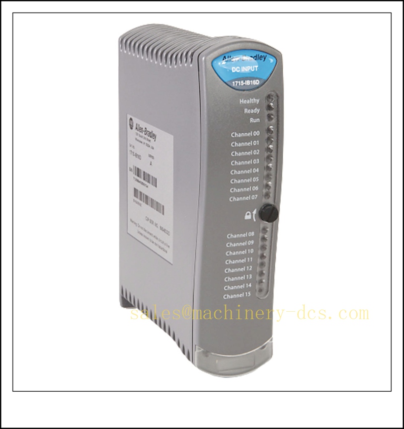
- 1715‑IB16D
- 1715‑IF16
- 1715‑OB8DE
- 1715‑OF8I
- 1715‑TASIB16D
- 1715‑TADIB16D
- 1715‑TASIF16
- 1715‑TADIF16
- 1715‑TASOB8DE
- 1715‑TADOB8DE
- 1715‑TASOF8
- 1715‑TADOF8
- 1715‑C2
Frequently Asked Questions
Q1: What is the main function of 1715‑AENTR?A: It is the EtherNet/IP gateway adapter for the 1715 redundant I/O system. It bridges Logix controllers and fault‑tolerant 1715 I/O racks and supports redundant network operation.
Q2: Can one 1715‑AENTR work alone for duplex I/O?A: Duplex redundant I/O architecture requires two 1715‑AENTR modules fitted on one 1715‑A2A base. Single adapter only supports simplex configuration.
Q3: Is 1715‑AENTR hot-swappable?A: It supports replacement under power on the 1715‑A2A base, but safety lockout procedures must be followed for field I/O loops. Redundancy health status should be monitored before removal.
Q4: What are common fault symptoms?A: Loss of EtherNet/IP connection, controller I/O timeout alarm, redundant switchover failure, adapter status LED fault, intermittent I/O freeze.
Q5: What is the warranty?A: Standard 12-month functional warranty. Warranty void for damage from miswiring, overvoltage, surge, ESD, improper redundancy configuration or physical port damage.
Installation & Configuration Guide
Important Reminder: Use ESD wrist strap all the time. Static discharge can damage Ethernet and backplane circuits.
- Preparation: Prepare 1715‑A2A base, screwdriver, Ethernet cables, RSLogix 5000 / Studio5000 engineering software and RSLinx. Perform lockout-tagout on field hazardous circuits.
- Base Installation: Mount the 1715‑A2A backplane on DIN rail and wire 24 VDC power supply.
- Adapter Insertion: Insert 1715‑AENTR into slot 0 and slot 1 of the A2A base for redundant pair; lock the module latches.
- Ethernet Wiring: Connect primary and secondary network ports to EtherNet/IP switch following redundant topology design.
- IP Address Assignment: Use BOOTP/DHCP or RSLinx to set static IP for the primary adapter. Secondary MAC/IP is automatically managed by the redundancy logic.
- Studio5000 Hardware Configuration: Add 1715‑AENTR redundant adapter pair in I/O tree, set RPI and safety parameters, download project to Logix controller.
- Commissioning Check: Verify adapter RUN, LINK and REDUNDANCY LEDs. Confirm all downstream 1715 I/O modules go online without connection faults.
- Switchover Test: Force primary adapter fault to test bumpless transfer and confirm no I/O drop.
- Asset Record: Log serial numbers, firmware version, IP address, rack slot and configuration revision for maintenance management.

 Send an Email