
Description
Allen‑Bradley 440L-R4F0018-Q is the receiver unit
Model: 440L-R4F0018-Q | GuardShield POC Type4 Safety Light Curtain Receiver
1. Product Title & Description
The Allen‑Bradley 440L-R4F0018-Q is the receiver unit of 440L GuardShield POC Type4 safety light curtain, part of Rockwell Bulletin 440L series safety presence sensing device. It works with matched transmitter to create infrared multi-beam safety detection zone. When beams are blocked by human body or objects, safety outputs will cut off hazardous machine motion immediately. Widely used for robot cells, stamping presses, packaging lines, material handling conveyors and automated machining workstations.
2. Core Product Overview
440L-R4F0018-Q is the receiver component for 440L safety light curtain system (R = Receiver). Together with the paired transmitter, it forms Type4 high safety category light curtain, compliant with ISO 13849-1 PL e. Detection range: 0.5m ~ 18m. It supports advanced safety functions: fixed blanking / floating blanking, beam coding, external device monitoring (EDM), start/restart interlock. Built-in LED status indicators for alignment, power and fault diagnostics. M12 quick connector for fast wiring. It can connect to safety relay or Guard I/O modules, integrates perfectly with Allen‑Bradley GuardLogix safety PLC and ControlLogix system (such as 1756-L73).
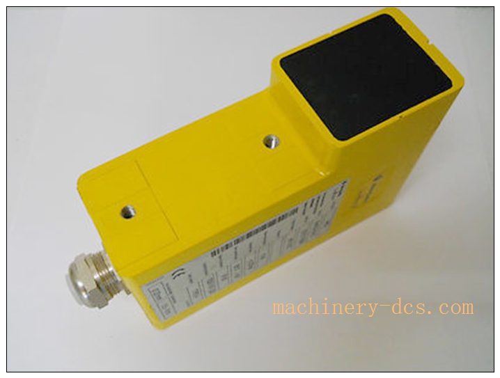
440L-R4F0018-Q
3. Main Technical Specifications
- Manufacturer: Rockwell Automation (Allen‑Bradley)
- Part Number: 440L-R4F0018-Q
- Product Type: GuardShield POC Type4 Safety Light Curtain Receiver
- Safety Category: Type4, PL e / SIL3
- Operating Range: 0.5 ~18 meters
- Supply Voltage: 24VDC
- Power Consumption: Max 6W
- Connection: M12 quick disconnect connector
- Housing Rating: IP65 (standard)
- Diagnostics: LED indicators for power, alignment, fault
- Supported functions: EDM external device monitoring, blanking, beam coding, auto restart / manual restart interlock
- Operating Temperature: -10°C ~ +55°C
- Storage Temperature: -40°C ~ +70°C
- Relative Humidity: 10% ~95%, non-condensing
- Certifications: CE, UL, cUL
4. Quality Control Procedures
Rockwell safety products comply with ISO9001, ISO13849 and IEC 61508 standards.
- Incoming Component Inspection: infrared receiver chips, safety logic IC, connectors and housing screening.
- Automated assembly, each unit with unique serial number for full lifecycle traceability.
- Full functional test: beam receiving test, safety output response, blanking function, EDM and fault diagnosis verification.
- Environmental stress screening: thermal cycling, vibration, dust and moisture aging test.
- Final inspection & packing: visual inspection, anti-static packaging and factory test certificate.
5. Brand Related Matching & Replacement Models
- 440L-T4F0018-Q: Matched transmitter for 440L-R4F0018-Q
- 440L series other height/range models: different protection height variants
- 1756-L73: ControlLogix CPU commonly used with safety light curtain system
- 1756-LSP / GuardLogix: Safety controller for safety system integration
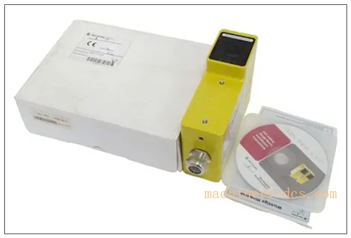
440L-R4F0018-Q
6. Frequently Asked Questions (FAQ)
Q1: Is 440L-R4F0018-Q transmitter or receiver? A1: Receiver (R suffix). Must be used together with corresponding 440L-T4F0018-Q transmitter as a complete set.
Q2: What safety level does this light curtain achieve? A1: Type4, PL e / SIL3, suitable for high-risk machine safeguarding applications.
Q3: What is the maximum working distance? A3: 18 meters. Minimum working distance 0.5m.
Q4: Can it work with ControlLogix PLC? A4: Yes, connect safety outputs to safety relay or Guard I/O module, then interface to GuardLogix / ControlLogix system.
Q5: What is the warranty for original Allen‑Bradley 440L-R4F0018-Q? A5: Original Rockwell unit carries standard 12-month factory warranty against manufacturing defects under proper installation and operation.
7. Installation & Configuration Guide
7.1 Pre-installation Preparation
Verify 440L-R4F0018-Q receiver and matching transmitter. Prepare mounting brackets, 24VDC power, M12 cable, safety relay or Guard I/O. Lock out machine power before installation. Check safety distance calculation according to machine risk assessment.
7.2 Installation Steps
Mount transmitter and receiver on both sides of hazardous zone with mounting brackets, ensure optical axes aligned. Wire 24VDC power and safety output wiring via M12 connector. Connect EDM circuit for monitoring external contactors. Route shielded cable and single-point grounding. Check no reflective surfaces nearby that cause false detection.
7.3 System Configuration & Commissioning
Power up the set, adjust position for proper beam alignment (alignment LED green). Configure restart interlock, blanking and EDM function according to machine safety requirement. Test beam interruption: when beam blocked, safety outputs must switch off immediately. Test auto/manual restart function and external device monitoring. Record safety test report.
7.4 Maintenance & Precautions
Periodically inspect lens for dust or scratch, check mounting bracket looseness and alignment. Clean lens regularly. Do not change safety wiring or disable safety functions arbitrarily. If fault occurs, check alignment, 24V power supply and reflective interference before replacing the receiver.

 Start Chat


 Send an Email


