
Description
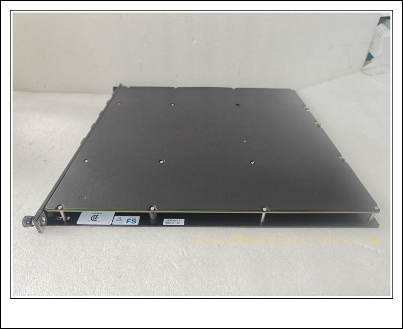
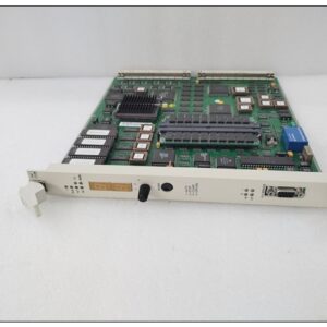
Triconex 4351B Tricon Communication Module (TCM), TMR Safety Gateway for Tricon SIS
Product Description
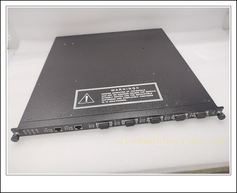
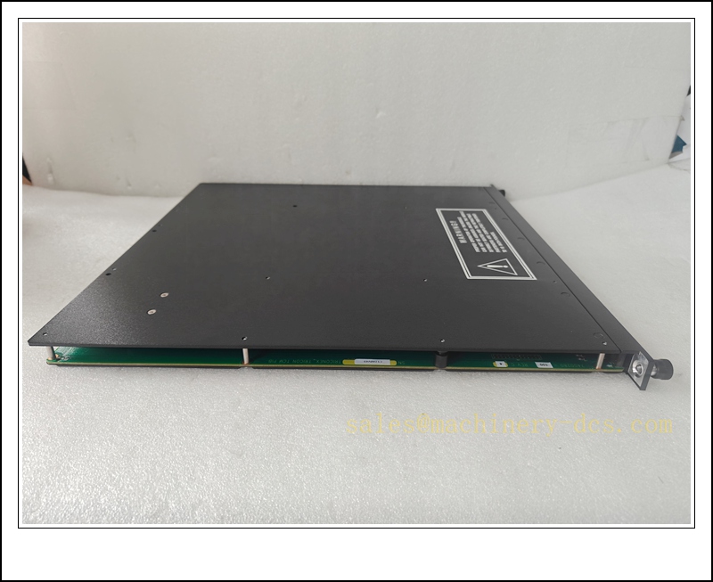
The Triconex 4351B is a Tricon Communication Module (TCM) built on triple modular redundant architecture for Tricon safety instrumented systems. It serves as a high-integrity communication gateway between Tricon TMR controllers, TriStation engineering workstations, DCS, HMI, Modbus field devices and peer Tricon racks. It carries 4 configurable serial ports and 2 10/100Base-T Ethernet ports, supporting Modbus RTU/TCP, TSAA, peer-to-peer synchronization, SNTP and GPS time sync. Each communication path is isolated from the safety backplane bus; communication faults do not affect the core 2oo3 safety voting logic. The module supports hot-swap within redundant TCM pairs, enabling online maintenance without shutting down the safety system. It is widely used for SOE timestamped event logging, system commissioning, remote diagnostics and cross-unit safety interlock coordination.
TRICONEX 4351B
Technical Specifications
- Brand: Triconex (Schneider Electric / Invensys Legacy)
- Model: 4351B
- Module Type: Tricon Communication Module (TCM)
- Architecture: TMR Triple Modular Redundancy, 2oo3 voting
- Port Configuration: 4 × RS232/RS485 serial DB9 ports; 2 × RJ45 10/100 Mbps Ethernet ports; 1 dedicated debug port
- Isolation: 500 VDC port-to-chassis galvanic isolation
- Supported Protocols: Modbus RTU/TCP, TSAA, Peer-to-Peer UDP/IP, SNTP, Trimble GPS, TriStation
- Aggregate Serial Bandwidth: Up to 460.8 kbps across four serial ports
- Backplane Interface: EICB Enhanced Intelligent Communication Bus
- Hot Swap: Supported when paired redundant TCM remains healthy
- Operating Temperature: 0 °C to +60 °C
- Storage Temperature: -40 °C to +85 °C
- Relative Humidity: 5%–95%, non-condensing
- Safety Certification: SIL 3 capable for Tricon platform, ATEX Zone 2, IECEx, UL, CE
- Compatible Chassis: Tricon 7-slot and 15-slot main / expansion chassis
- Power: Powered via Tricon chassis backplane
- Weight: Approx. 1.62 kg
Application Scenarios
- Petrochemical and refinery ESD systems for DCS/HMI interface and SOE event logging
- Onshore and offshore oil & gas fire & gas SIS, cross-platform peer-to-peer safety interlock
- Power plant turbine and boiler safety systems, time-synchronized trip sequence recording
- LNG and cryogenic terminal safety instrumented system integration
- Pipeline remote unmanned SIS panels and Modbus field device communication
- Chemical plant unit-to-unit safety cascaded shutdown coordination
- Hazardous Class I Div 2 / Zone 2 control cabinets for safety network gateway
- Spare replacement and maintenance of existing Tricon SIS running v9.6 and above firmware
8 Related Triconex Model Recommendations
- 4352B – Fiber Ethernet Tricon Communication Module
- 4353 – Advanced TCM with embedded OPC server
- 3805E – Tricon Main Processor Module
- 8310 – 120VAC/VDC Tricon Power Supply
- 8311 – 24VDC Tricon Power Supply
- 3703E – 8-Channel Analog Input Module
- 3704E – 8-Channel Analog Output Module
- 3721 – Tricon Communication Interface Module
Compatibility & Installation Pitfalls
Compatibility
- Designed exclusively for Tricon TMR chassis; not compatible with Trident racks or Bently Nevada 3500 racks.
- Requires Tricon firmware v9.6 or newer; older Tricon revisions cannot recognize this TCM variant.
- Best practice is dual redundant TCM deployment; single-module operation is only for temporary maintenance.
- It occupies a dedicated communication slot; cannot substitute processor or I/O slots.
- It handles external data exchange only; it does not execute safety logic, which remains on the 3805E processor triplet.
- Firmware revision must match the Tricon main processors to preserve SIL integrity.
Installation Pitfalls
- Hot-swap is allowed only if the second redundant TCM is online and healthy. Never remove the last active communication gateway while safety sequences depend on external interlocks.
- Serial ports are software-configurable between RS232 and RS485; incorrect wiring or termination resistors cause intermittent Modbus timeouts.
- Ethernet ports are 10/100 copper only; 4351B cannot use fiber media — select 4352B for fiber networks.
- Communication cable segregation is mandatory; serial/Ethernet wiring must be routed separately from high-power AC/VFD cables to avoid EMI and packet loss.
- GPS time sync is available only on serial port 1; port 4 is reserved for TriStation engineering download by default.
- Port isolation protects the safety bus, but the module itself is not a firewall; external network security controls are required for untrusted hosts.
- Mismatched TCM firmware versions in a redundant pair lead to out-of-sync SOE timestamps and peer communication failures.
- Debug port is factory service-only; connecting it to user networks may trigger unexpected diagnostic behaviours.
TRICONEX 4351B
Standard Operating Procedure (SOP)
SOP for 4351B Communication Module Inspection, Installation and Functional Test
- Pre-Installation Inspection Inspect the module for physical damage, bent DB9/RJ45 connectors or contamination. Confirm the part number 4351B and verify Tricon chassis firmware compatibility. Review network drawings, Modbus register alias configuration and redundant TCM architecture. Apply lockout-tagout if removing the last operational communication gateway supporting safety interlocks.
- Rack Installation Power down the chassis if replacing the final active TCM. Insert the 4351B into the dedicated TCM slot and secure fasteners. Terminate serial and Ethernet cables following approved EMC practices, with proper 120 Ω termination resistors for RS485. Separate communication cabling from high-energy power circuits per SIS documentation.
- Software Configuration Launch TriStation and connect to the Tricon rack. Map the 4351B in the system I/O configuration. Define port roles: Modbus master/slave, GPS sync, peer-to-peer or TriStation engineering. Configure Modbus aliases, IP addresses, SNTP and SOE capture parameters. Download the validated configuration to the Tricon processor triplet and resolve firmware mismatch alarms. Archive the network configuration for IEC 61508 audit traceability.
- Communication and Diagnostic Test Verify Ethernet link status and serial port handshake. Test Modbus read/write operations with field devices and confirm data consistency. Simulate loss of the redundant paired TCM to confirm the remaining 4351B maintains all data links and SOE logging. Verify fault indicators report link loss and module health correctly. Record communication latency and diagnostic behaviour in the SIS maintenance log.
- System-Wide Interlock Verification Confirm safety logic, analog and discrete I/O continue to execute while communication links are cycled. Validate that communication channel faults trigger maintenance alarms only and do not initiate undesired ESD trips. Check cross-Tricon peer interlocks and time-stamped SOE records under normal and fault conditions.
- Return to Service Clear temporary fault latches and alarm acknowledgements. Remove lockout-tagout as applicable. Monitor link status, timestamp accuracy and port health through the required observation window. Notify operations that Tricon safety communication gateway is online.
- Periodic Maintenance and Replacement During planned outages, inspect connector torque, cable shielding and network switch health. Execute redundant TCM failover testing per the site SIS proof-test schedule. If the 4351B reports persistent non-resettable bus faults, confirm the redundant partner TCM is fully healthy before hot-swap. After replacement, verify link operation, Modbus exchange, SOE timestamp synchronization and peer communication before releasing the rack to safety duty.


 Start Chat


 Send an Email


